
Chapter 14: Bit Rotation, Shifting, Clearing
Other than Logical Operations, other bitwise type operations include Bit Rotation, Shifting, and Clearing.
Clearing bits:
Clearing is very simple. All it means is any bit(s) are to be set low. For example, let's say we have the value 0x12347F00 in w5. In binary view, this would be..
0001 0010 0011 0100 0111 1111 0000 0000
Let's say we clear the lower (right-side) 10 bits. The result would be...
0001 0010 0011 0100 0111 1100 0000 0000
Result in hex is now 0x12347C00. Notice the bits in red. Those bits were set low. Any bit that is already zero, remains as zero when cleared.
ARM64 has the bic (Bit Clear) instruction. You've learned about this instruction in the previous chapter. To recap, this instruction will use the value provided in the 2nd Source Register or Immediate Value, and whatever bits are high in that Value will clear the corresponding bits in the 1st Source Register. Result placed in Destination Register.
Example:
bic w0, w1, w2
w1 = 0x0000FFF0
w2 = 0x0003007C
w0's value before the instruction executes is irrelevant as it will be completely overwritten.
w1 in binary form is...
0000 0000 0000 0000 1111 1111 1111 0000
w2 in binary form is...
0000 0000 0000 0011 0000 0000 0111 1100
Take note of the green binary 1's. These 1's indicate which bits are to be cleared in w1. Now let's say the instruction gets executed. The result (w0) is 0x0000FF80. In binary form, that is...
0000 0000 0000 0000 1111 1111 1000 0000
As you can see the green bits in w0 were the ones that were cleared by what was in w2. You will notice some bits that were cleared on w1 were already 0 beforehand. Remember any 0 bits that are cleared will remain as 0.
Shifting bits:
ARM64 comes with the following shifting instructions
lsl xD, xD, xB
lsl wD, wA, wB
lsl xD, xA, uimm
lsl wD, wA, uimm
lsr xD, xD, xB
lsr wD, wA, wB
lsr xD, xA, uimm
lsr wD, wA, uimm
asr xD, xA, xB
asr wD, wA, xB
asr xD, xA, uimm
asr wD, xD, uimm
uimm = any number from 0 to 63 for extended register usage, and any number from 0 to 31 for non-extended register usage.
xB and wB must contain values that will be in that uimm range as well.
lsl = Logical Shift Left
lsr = Logical Shift Right
asr = Arithmetic/Algebraic Shift Right
----------
Let's cover the lsr (Logical Shift Right) instruction first. Here's an example...
lsr w0, w0, #15
Pretend r5 (before the instruction gets executed) has the value of 0x0000FE1F. In binary that is...
0000 0000 0000 0000 1111 1110 0001 1111
Take note of the magenta 1. When the instruction executes, the result (in binary) is now this..
0000 0000 0000 0000 0000 0000 0000 0001
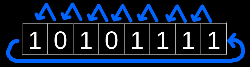
Thus r5 (in hex) is 0x00000001. Notice where the magenta 1 is at now. It has moved over to the right by 15 bits. When bits are shifted to the right, any bits that would go beyond the LSB are tossed away. The bits in blue are new bits that were put into the value because due to the right shift of 15 bits, the far left (upper 15 bits) were now missing and have to be replaced. In logical shifting, new bits that are used for this replacement are always low (zero) bits.
Here's a picture using arrows to give you a better visual of the mechanics of a Logical Shift Right
-----------
For the lsl (Logical Shift Left) instruction, any bits that go beyond the MSB are tossed away. New (zero) bits will have to replace missing far right (lower) bits.
Example:
lsl w6, w6, #2
w6 (before the instruction executes) is 0x80000007. In binary that is..
1000 0000 0000 0000 0000 0000 0000 0111
Take note of the upper 2 bits colored in red. After instruction is executed, the result is 0x0000001C. In binary, that is...
0000 0000 0000 0000 0000 0000 0001 1100
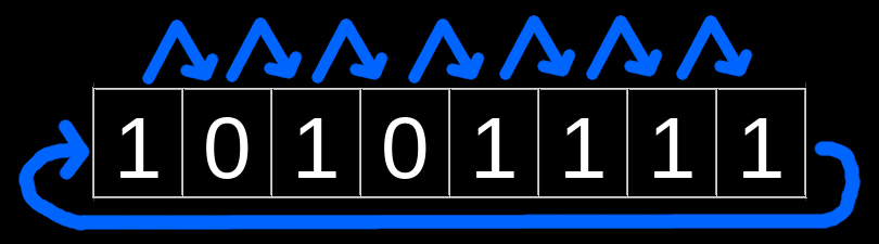
Hex result is 0x0000001C. The red upper 2 bits were thrown away because it was shifted beyond past the MSB. The blue bits were the new (zero/low) bits that had to be placed in.
Here's a picture with arrows~

----------
Let's cover the asr instruction. It operates just like lsr, however when the bits are shifted to the right, the Destination Register's MSB value (what is was before the shift) will be copied into any new bit slots that were opened up on the left hand side due to the rightward shift. Confused? Let's over go an example.
asr w0, w3, #3
Pretend w3 starts off with the value of 0xFFFFFFF0. In binary, that is...
1111 1111 1111 1111 1111 1111 1111 0000
Take note of bit 31 (MSB) in green. It's value will be use as the 'copy value' for new bit slots that will be opened up by the rightward shift.
Now let's say we execute the instruction. The result in w3 is 0xFFFFFFFE. In binary, that is...
1111 1111 1111 1111 1111 1111 1111 1110
Notice that bits 31 thru 28 are in orange. These bits are copies of previous bit 31's value (what bit 31 was before the rightward shift; highlight in green).
Here's a picture with arrows~

Bit Rotation:
Now that you understand shifting, rotation will be easy to learn. So in shifting, when bits go beyond the MSB or LSB, they are tossed away (or copied in the case of asr). In rotation, they are instead recycled.
Here's 4 pics showing the difference between shifting & rotating~
Pic 1: Shift Left
Pic 2: Rotate Left
Pic 3: Shift Right
Pic 4: Rotate Right
ARM64 comes with following ror instructions for right-hand bit rotation.
Rotate Right:
ror xD, xA, xB //xB must contain a value from 0 thru 63
ror wD, wA, wB //wB must contain a value from 0 thru 31
ror xD, xA, uimm // uimm = anything from 0 thru 63
ror wD, wA, uimm // uimm = anything from 0 thru 31
Keep in mind, that this instruction does a ***RIGHT*** rotation, *not* a left rotation.
Let's say we have the following instruction
ror w5, w7, w9
Before the instruction executes...
w7 = 0x7F7F7F00
w9 = 23 // The amount to Rotate Right by
w7 in binary form is...
0111 1111 0111 1111 0111 1111 0000 0000
Each group of four is uniquely colored, take note.
Once the instruction has executed, w5 gets the result, which is 0xFEFE00FE. Let's examine w5 in Binary view..
1111 1110 1111 1110 0000 0000 1111 1110
The colors show us how the bits were rotated to come up with the new result.
Bit Extraction:
Bit extraction is a non-arithmetic shift where a portion of the regular post-shift leftover bits are selectively kept intact. The other bits are set low.
Another way of thinking about Bit Extraction, is "grabbing" a chain (consecutive field) of bits out of a register, and moving that field of bits to a register (or different location within same register). All other bits, which we can call the "unrelated" bits, are CLEARED/ZEROED.
If these "grabbed" bits are placed at the far left of a register, this is known as Left Justification.
If these "grabbed" bits are placed at the far right of a register, this is known as Right Justification.
ARM64 comes with some Bit Extraction instructions. The most commonly used one is ubfx (unsigned bit field extract)
ubfx xD, xA, #LSB, #Width //LSB & width cannot exceed 63
ubfx wD, wA, #LSB, #Width //LSB & width cannot exceed 31
Width = the bit field size for the extraction.
LSB = This is the ending bit in the Source Register (wA/xA) of the bit field.
NOTE: *ALL* ARM64 bit-extraction type instructions ONLY do right justification.
Let's go over an example of ubfx. We have the following instruction...
ubfx w1, w0, #18, #7
w0's value is 0x00AC6874 BEFORE the instruction executes. Binary View of w0 is...
0000 0000 1010 1100 0110 1000 0111 0100
Take note of the bits in purple. You will see the purple field of bits is 7 bits in size, This matches the "#7" value for the width used in the ubfx instruction. You will see the far right bit of the purple bit is at bit 18. This matches the "#18" value for the LSB used in the ubfx instruction
After the instruction has executed, the result (placed in w1) is 0x0000002B. In binary form, this is....
0000 0000 0000 0000 0000 0000 0010 1011
As you can see, the purple bits are aligned to the far right when placed into w1. The bits that aren't part of the "grabbed" bits are always set low (zero).
-----
ARM64 also comes with a Signed version of ubfx that is called sbfx (Signed Bitfield Extract)
sbfx xD, xA, #LSB, #Width //LSB & width cannot exceed 63
sbfx wD, wA, #LSB, #Width //LSB & width cannot exceed 31
Width = the bit field size for the extraction.
LSB = This is the ending bit in the Source Register (wA/xA) of the bit field.
LSB and Width operate the exact same as ubfx. In typical extraction instructions. whatever bits (in the Destination Register) that aren't part of the extracted field are usually set low. The difference in sbfx is that these "other bits" are set to the bit value of the MSB of the field that is extracted. Confused? Let's re-do the same example we went over for ubfx but instead use the sbfx instruction...
sbfx w1, w0, #18, #7 //Pretend w0 = 0x00AC6874 before the instruction executes.
Let's look at 0x00AC6874 in binary form....
0000 0000 1010 1100 0110 1000 0111 0100
Take note of the green zero. This is the MSB of the field of bits that will be extracted. The rest of the to-be extracted bit field is in purple. When execution of this instructions occurs, that field's MSB value will get copied to all other bits of the Destination Register that aren't used for the grabbed/extracted bit(s) placement. Let's say the sbfx instruction executes. w1's result is 0x0000002B. In binary that is...
0000 0000 0000 0000 0000 0000 0010 1011
The green bit and the purple bits is the extracted field. The yellow bits is what was copied to the rest of the bits in the Destination Register.
Now let's redo this same instruction but use a slightly different value in w0sbfx w1, w0, #18, #7 //Pretend w0 = 0x01AC6874 before the instruction executes.
w0 in Binary is...
0000 0001 1010 1100 0110 1000 0111 0100
Take good note of the green binary 1. This will be the bit that gets copied. In more proper terms, this is the bit used for the "sign filling" of the Destination Register. Now let's say we execute the instruction, w0's result is 0xFFFFFFFEB.
In Binary that is..
1111 1111 1111 1111 1111 1111 1110 1011
As you can see, the green was used as the sign-filled bit to copy to the rest of the register which is indicated by the yellow bits.
Bit Insertion:
Standard Bit insertion is simply a consecutive field of bits that is placed into a register that will overwrite an existing field while leaving all other bits alone. Keep in mind there are different types of bit insertions, let's cover standard bit insertion first...
Bit Field Insert:
bfi xD, xA, #LSB, #Width //LSB & width cannot exceed 63
bfi wD, wA, #LSB, #Width //LSB & width cannot exceed 31
Width = the bit field size for the insertion. ***All*** bit fields used in Source register are RIGHT JUSTIFIED!
LSB = Tells the instruction where to insert the field at into the Destination Register. The field will insert at the Destination Register's LSB where the field's far right bit will be at the LSB.
For example, let's say we have the following instruction...
bfi w5, w4, #9, #6
Pretend w4 in binary is this...
0000 0000 1010 1100 0100 1110 0111 0100
Pretend w5 in binary is this BEFORE the instruction executes...
1111 0000 1111 0000 0101 0101 0101 0101
Take note of the bits in BLUE for w4. This is the field that will be used for the insertion. Take note of the bits in RED for w5, this is where the field will be inserted at. Meaning these bits and only these bits in w5 will be replaced.
After the instruction as executed, w5 is now....
1111 0000 1111 0000 1101 0001 0101 0101
The field inserted is shown via the blue bits. As you can see, all other bits in the Destination Register were left alone.
-----
ARM64 has a bfc (bit field clear) instruction. It operates the exact same as bfi except the bitfield that is inserted is always made up of zeroes.
Bit Field Clear:
bfc xD, #LSB, #Width //LSB & width cannot exceed 63
bfc wD, #LSB, #Width //LSB & width cannot exceed 31
Width = the bit field size for the insertion. ***All*** bit fields used in Source register are RIGHT JUSTIFIED!
LSB = Tells the instruction where to insert the zero-field at into the Destination Register. The zero-field will insert at the Destination Register's LSB where the field's far right bit will be at the LSB.
As you can see, there is no Source Register because a bitfield of zeroes is always used in the insertion. The bfc instruction operates similarly to the bic instruction. Since the bic instruction cannot use Immediate Values, it may be better to use the bfc instruction instead.
For example, a beginner who needs to clear bits 15 thru 12 of a non-extended register (let's say w1) may write something like this..
movz w18, 0xF000 // Set the bitfield using w18 as a scratch register
bic w1, w1, w18 // Clear bits 15 thru 12 of w1. Bits to clear are indicated in the high-bits present in w18
You can shorten the above code using just a single bfc instruction, like this...
bfc w1, 12, 4 // Width of 4 bits using LSB at bit 12 will set the zero'd bitfield at bits 15 thru 12
-----
If you need to do bit insertion but instead of leaving the unrelated bits unchanged (i.e. bfi instruction), you can have said bits all be changed to zeroes. This is done via the ubfiz instruction.
Unsigned Bitfield Insert into Zeroes:
ubfiz wD, wA, #LSB, #Width //LSB & width cannot exceed 63
ubfiz wD, wA, #LSB, #Width //LSB & width cannot exceed 31
Width = the bit field size for the insertion. ***All*** bit fields used in Source register are RIGHT JUSTIFIED!
LSB = Tells the instruction where to insert the field at into the Destination Register. The field will insert at the Destination Register's LSB where the field's far right bit will be at the LSB.
Let's redo the same example we used for the bfi instruction but instead use a ubfiz instruction
ubfiz w5, w4, #9, #6
Pretend w4 in binary is this...
0000 0000 1010 1100 0100 1110 0111 0100
Pretend w5 in binary is this BEFORE the instruction executes...
1111 0000 1111 0000 0101 0101 0101 0101
Bits in BLUE for w4 is the field that will be used for the insertion. The bits in RED for w5 is where the field will be inserted at. The other bits in w5 will be set to zero ***ONCE*** the instruction has executed.
Now let's say the instruction executes, w5 is now 0x000D0000. In Binary, that is...
0000 0000 0000 0000 1101 0000 0000 0000
Bits in BLUE was the bitfield that was inserted from w4. Bits in ORANGE were the bits that aren't part of the bitfield insertion and are thus set low (to 0's).
------
We have yet another bitfield insertion type instruction in ARM64. That is sbfiz...
Signed Bitfield Insert into Zeroes:
sbfiz wD, wA, #LSB, #Width //LSB & width cannot exceed 63
sbfiz wD, wA, #LSB, #Width //LSB & width cannot exceed 31
Width = the bit field size for the insertion. ***All*** bit fields used in Source register are RIGHT JUSTIFIED!
LSB = Tells the instruction where to insert the field at into the Destination Register. The field will insert at the Destination Register's LSB where the field's far right bit will be at the LSB.
sbfiz does the same thing as ubfiz, except the bits on the lefthand side of the inserted bitfield of the Destination Register are Sign-Filled. The bits on the righthand side of the inserted bitfield are still set to zero!!!
Let's yet again re-do the same example we did for bfi & ubfiz with the same registers and values, but run it with a sbfiz instruction instead.
sbfiz w5, w4, #9, #6
Pretend w4 in binary is this...
0000 0000 1010 1100 0100 1110 0111 0100
Pretend w5 in binary is this BEFORE the instruction executes...
1111 0000 1111 0000 0101 0101 0101 0101
Bits in BLUE for w4 is the field that will be used for the insertion. The bits in RED for w5 is where the field will be inserted at.
Now let's say the instruction executes, result in w5 is 0xFFFD0000. In Binary, that is...
1111 1111 1111 1111 1101 0000 0000 0000
Bits in BLUE was the bitfield that was inserted from w4. Bits in YELLOW are the bits that are to the left of the inserted bitfield that are set high (to 1's), aka the Sign-filled bits. Bits in ORANGE were the ones to the right of the inserted bitfield and are thus set low (to 0's).
Bit Extraction + Insertion:
ARM64 comes with a instruction that does both an extraction then an insertion. This is the bfxil (Bit Field Extract then Insert Low) instruction...
bfxil xD, xA, #LSB, #Width //LSB & width cannot exceed 63
bfxil wD, wA, #LSB, #Width //LSB & width cannot exceed 31
The bfxil does the following...
You can think of the bfxil instruction as a ubfx instruction first, *then* a bfi instruction second.
For example, let's say we need to extract bits 31 thru 25 of w7. We then need to insert those bits into w24, right justified. A beginner may write the code like this...
ubfx w17, w7, 25, 7 #Extract bits 31 thru 25 of w7 and temporarily place them into w17 (scratch register)
bfi w24, w17, 0, 7 #Insert the extracted bits into w24, right justified. Thus they are inserted at bits 6 thru 0 of w24.
Using bfxil, we can do the above in a single instruction. Like this...
bfxil w24, w7, 25, 7
Fast Division and Multiplication:
Obviously ARM64 comes with dedicated multiply and divide instructions. The issues with these instructions (especially with the divide instructions) is that they take a long time for the CPU to execute. Shifting instructions can be used in place of *some* multiplication and division. Shifting instructions execute much faster than dedicated multiply and divide instructions. So if you ever run into a situation in the future where you need the CPU to be fast fast, this will be helpful.
You can use a lsl instruction in place of a multiply instruction when you need to multiply a number by a power of 2. Power of 2 means to multiply a number by 2, or 4, or 8, etc etc.
Look at the following template below..
For unsigned division, you can use the lsr instruction...
For signed division, you can use the asr instruction...
Final Exercise:
Now that you know how to do various bit work. Let's go over an example of basic extraction, editing the extracted field, then re-inserting. Let's pretend we have a register (w25), and it is split into variable length of bit fields.
Let's pretend bits 20 thru 13 is a field that we need to increment by the value of 1. We cannot use a basic Add Immediate instruction. Regardless of what immediate value we try to supplement in the Add Immediate instruction, it will overwrite unrelated bits.
Thus, we need to extract the bit field, add 1 to it, then re-insert. Let's pretend we are using w0 as a scratch register. The code to do this will be...
ubfx w0, w25, #13, #8 //Extract bits 20 thru 13. Place the field into w0 right justified.
add w0, w0, #1 //Increment the field by 1
bfi w25, w0, #13, #8 //Re-insert the field
Welp that's it for this hefty Chapter. Onto the next one!