Chapter 7: Basic Instructions
We can finally get into some actual Assembly instructions. This will be a pretty hefty chapter. Please take your time. A great first instruction to learn would be the add instruction.
Add:
add rD, rA, rB
In the add instruction, the value in rA is added with the value in rB. The result of this addition is placed into rD. Whatever value that was in rD beforehand, is overwritten.
Example add instruction:
add r3, r10, r7
Value in r10 is added with value in r7. Result placed in r3.
Let's pretend that before the instruction has executed r10 = 2, and r7 = 3. What's currently in r3 is not a concern for us, as it will be overwritten once the instruction has executed.
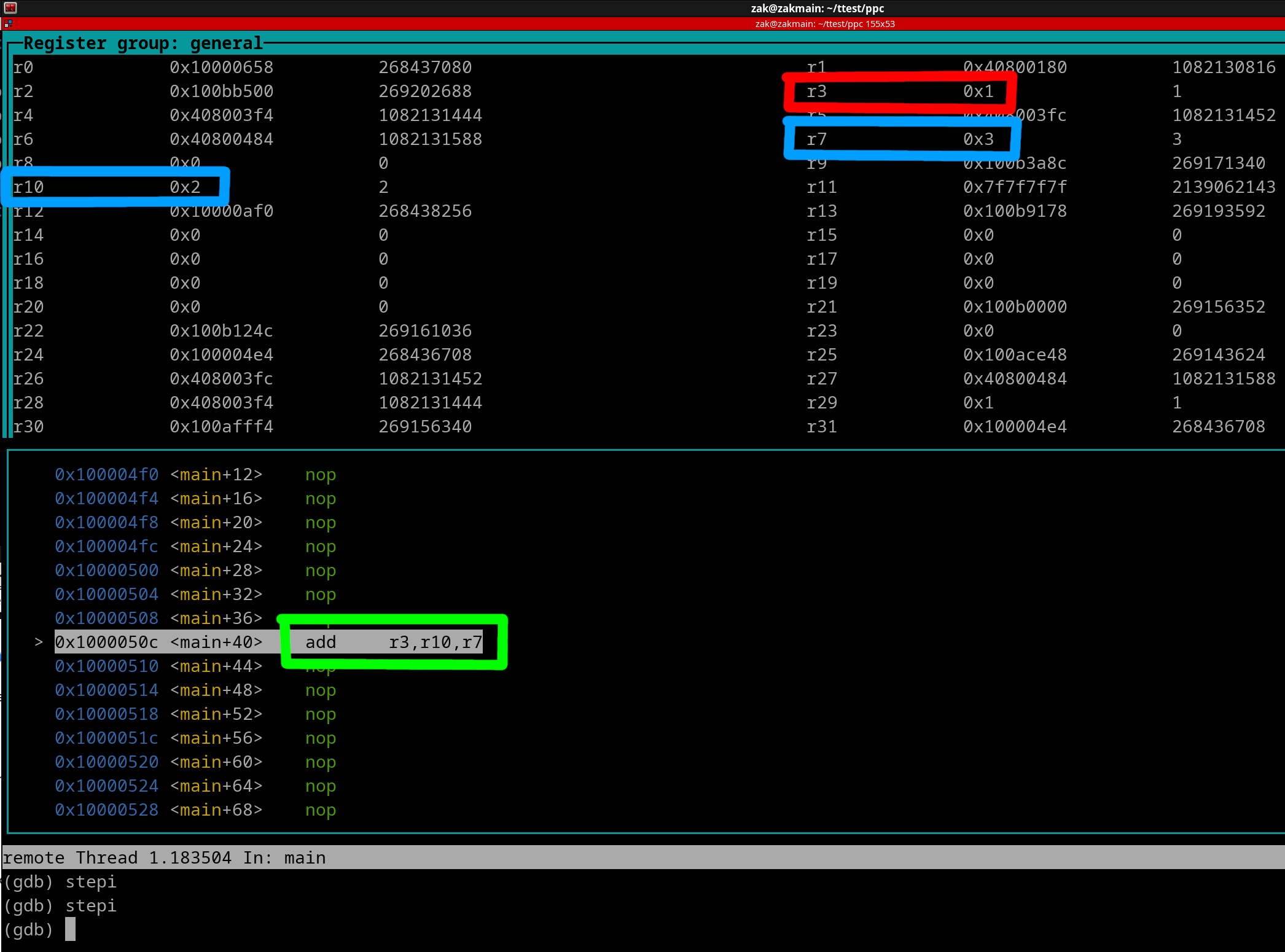
The picture below shows you an instance of this instruction right before it is executed. Both Source registers are outlined in blue, and the Destination Register is outlined in red. The add instruction is outlined in green.

Some things to unpack from the above Pic:
The above is a screenshot from a tool called GNU-Debugger (GDB). You've installed this tool to your Linux Machine back in Chapter 2. I'm using this tool with custom made Assembly Programs/Code to use for various instruction examples. You will start using this tool in Chapter 9. Each register will have its Hex and Decimal equivalent values listed. You can see the Hex values are on the near right for each corresponding Register, while the Decimal equivalents are on the far right. Another thing to keep in mind is that the Decimal values are always 32-bit Unsigned equivalents. This property of the Debugger that can't be changed/modified. Finally let's discuss the instruction outlined in green. You will see some information to the left of the instruction. The Hex Value that's incrementing by 4 is the Program Counter. The "start+68" is simply a reference point to in regards to the start of the Program. We'll discuss the nop instructions shortly.
Anyway, once the instruction gets executed the addition of 2+3 will be performed. The result of 5 is placed into r3. View the following picture...
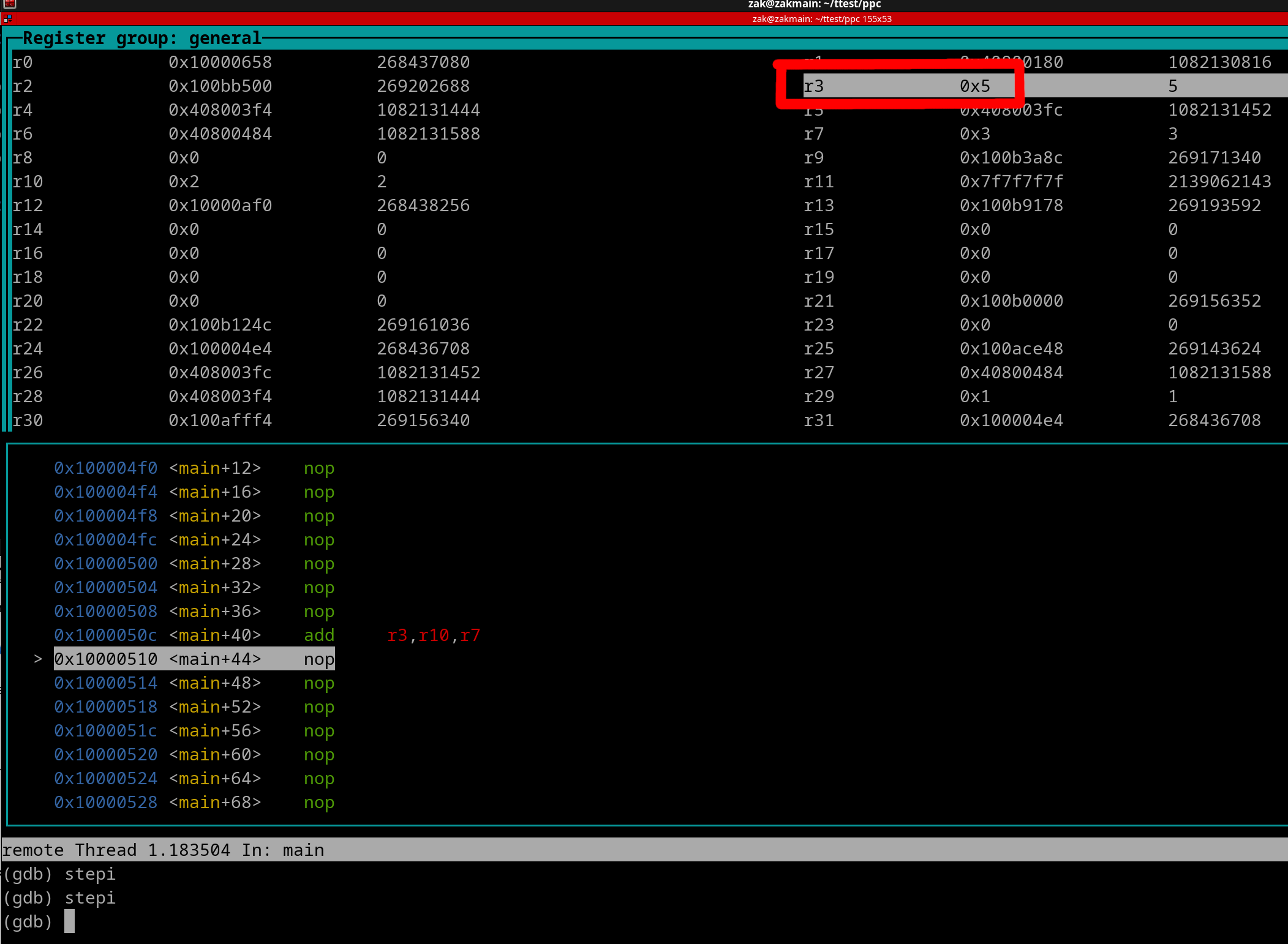
The result of 5 being placed in r3 is outlined in red.
Back in the previous Chapter, I've mentioned about Signed vs Unsigned issues. Well for the add instruction, there is no Signed or Unsigned "treatment" of values when the addition is performed. For example, if we add 0xFFFFFFFF + 0xFFFFFFFF, the result is always 0xFFFFFFFE.
If we pretend to "treat" the values as Signed this is easy to conclude as to why the result ends up as 0xFFFFFFFE (-2). Because -1 + -1 = -2. Simple. If we pretend to "treat" the Values as Unsigned, the result is still 0xFFFFFFFE. What occurs is that since the GPR cannot exceed 32-bits in width/size an event known as a "Carry" occurs. As a beginner, you do not need to know about Carry's for now, you will learn about them in Chapter 16. Just understand that there is no difference to the result placed in the Destination Register when it comes to Signed Vs Unsigned for the add instruction. Therefore, there's no such thing as Signed vs Unsigned number treatment for the actual addition within the add instruction. A majority of instructions follow this same concept.
Regarding the nop instruction, it simply tells the CPU to do nothing, literally. It can serve a variety of purposes. I'm simply inserting nop everywhere as having other unrelated possible complex instructions everywhere may be "visually cumbersome".
Let's move onto a slightly different instruction. That is the "Add Immediate" instruction.
Add Immediate:
addi rD, rA, SIMM
Example:
addi r12, r12, 0x1
The value in r12 is added with 1. The result of this addition in rewritten back into r12. That is because the register used for the Destination Register is the same register used for the Source Register. Thus r12 will simply be incremented by 1. Let's pretend r12 was the value of 7 before the instruction was executed. View the following picture...
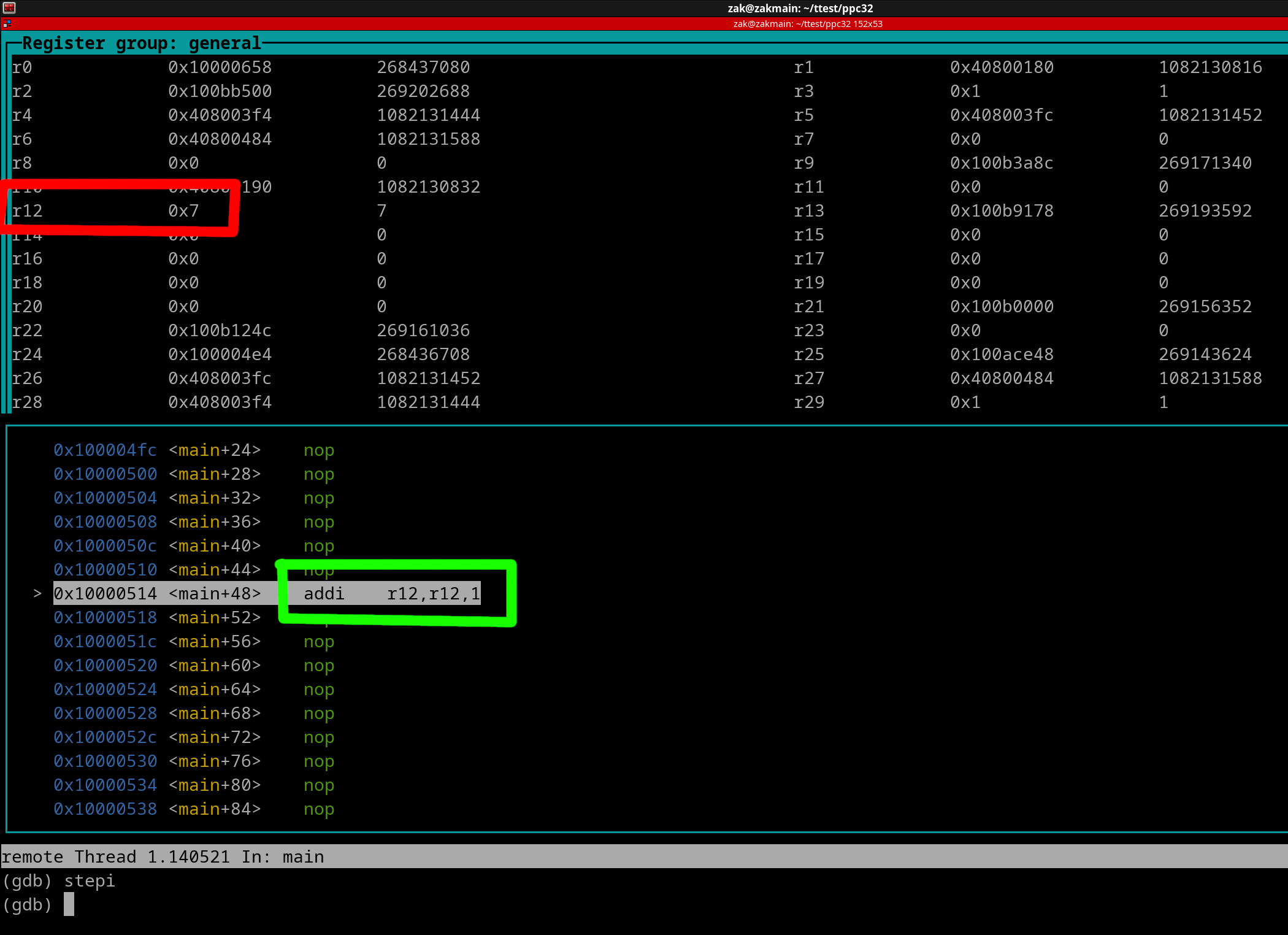
We can see r12 (outlined in red) is 7 but the addi instruction (outlined in green) hasn't been executed yet. Now, when the addi instruction does execute, r12 will be incremented by 1 as shown by the following picture...
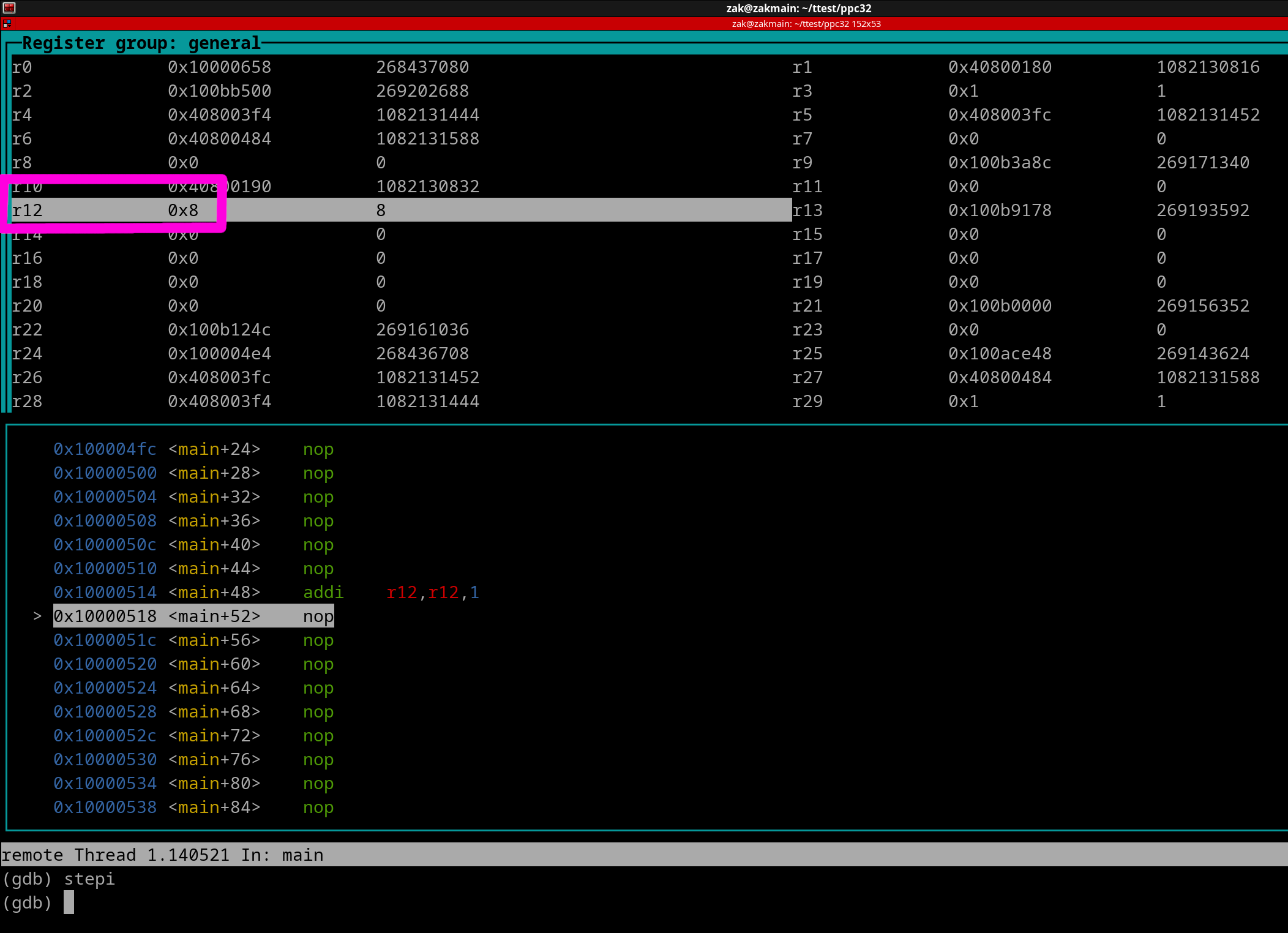
As you can see, r12 (outlined in magenta) has been incremented by 1 and now contains the value of 8.
Since addi uses SIMM for the Immediate Value, you can implement negative values like so...
addi r9, r6, -12 #Add negative 12 to value in r6. Result placed into r9.
However, we can write the above instruction like this...
subi r9, r6, 12 #Subtract 12 from r6. Result placed into r9.
The subi instruction is technically not a "real" instruction. It is a simplified mnemonic. A simplified mnemonic is an alternative instruction name/scheme used in place of the original. The two above instructions are exactly the same.
Subtract & Subtract Immediate:
sub rD, rA, rB #rD = rA - rB
subi rD, rA, SIMM #rD = rA - SIMM
Let's go over a "subi r9, r6, 12" instruction. Assume r6 = 0x00000000B (11). Here's a pic of right before the instruction has executed.
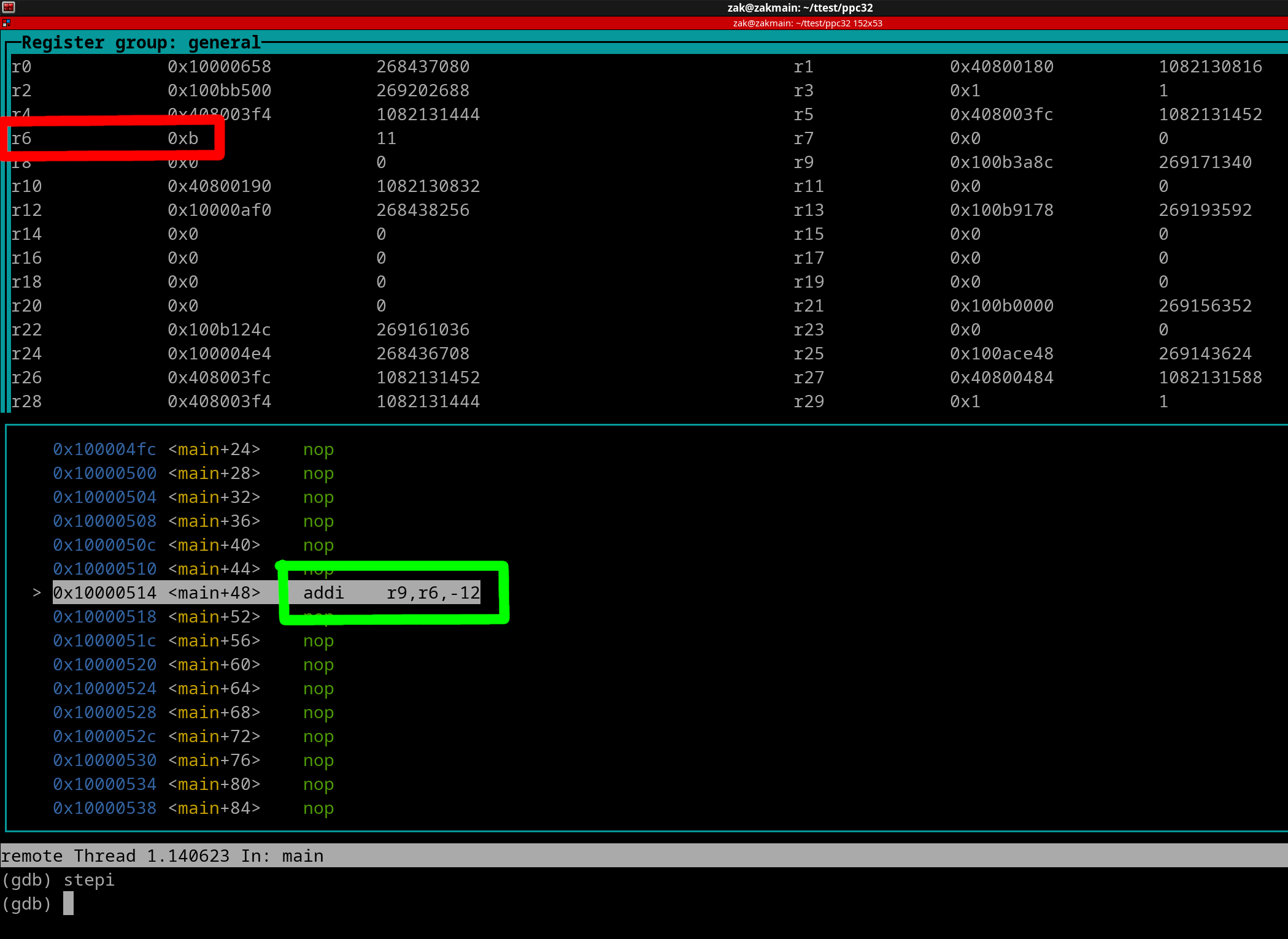
NOTE: GDB prefers to display the standard mnemonic (addi) over subi.
We can see r6 (outlined in red) is 11, but the subi (addi) instruction (outlined in green) hasn't been executed yet. Now let's execute the instruction, and see the result in the following pic......
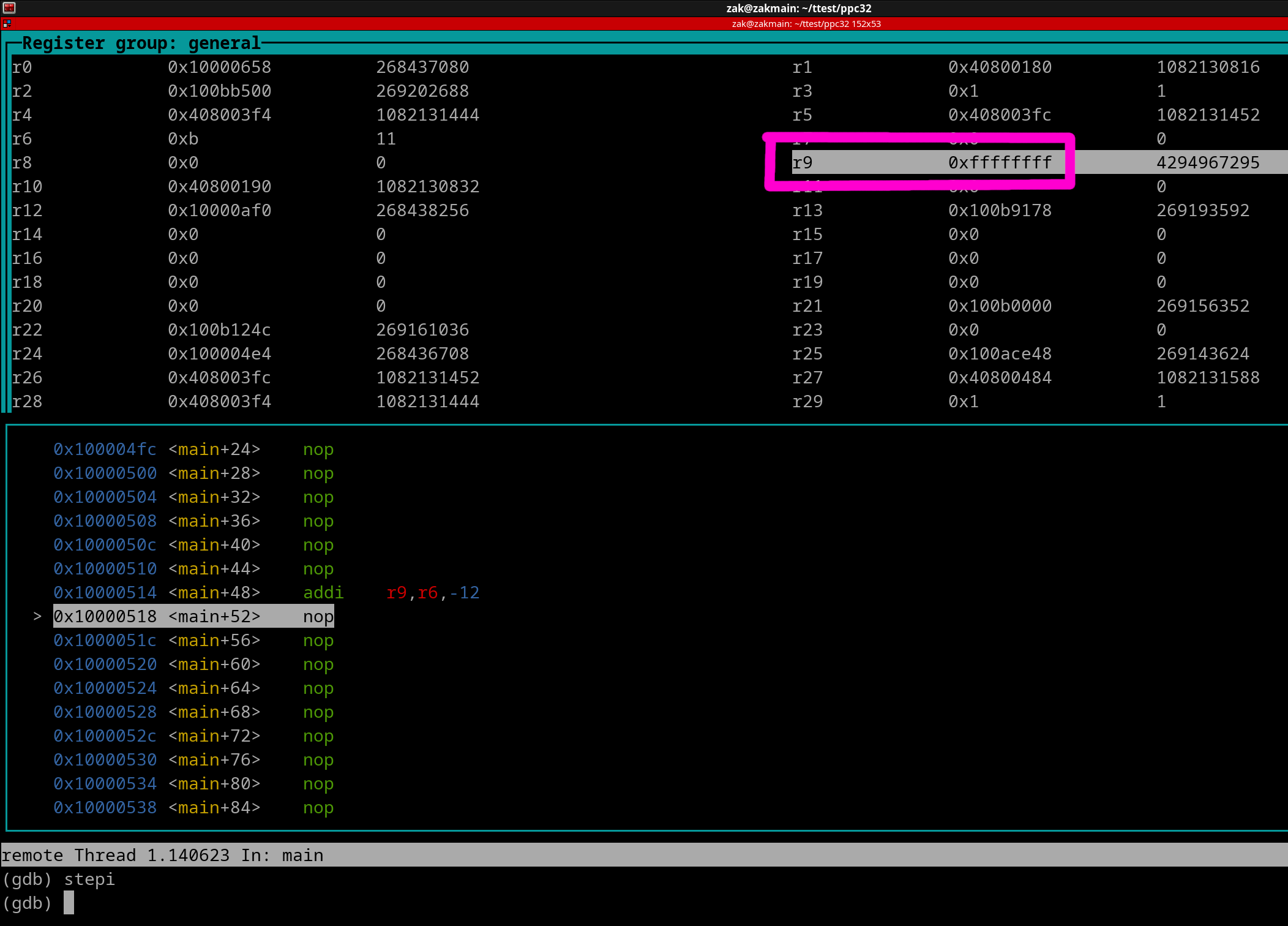
The result (0xFFFFFFFF aka -1) is outline in magenta. How did this result occur? Well, 11 - 12 = -1. Negative 1 is represented as 0xFFFFFFFF in a GPR.
Let's go over another common instruction.
Load Immediate:
li rD, SIMM
This is a simplified mnemonic. You can see there is no source register.
li rD, SIMM = addi rD, r0, SIMM
You may be asking yourself, what if a non-zero value is in r0? Wouldn't that effect the addi operation?
NO it wouldn't. PowerPC has a weird quirk. For certain instructions, if r0 is used as a source register, it is treated as Literal Zero. Here's a full list of all instructions that treat r0 as literal zero - LINK
Now let's go over an example of Load Immediate
li r6, 0xFF
Once the instruction has execute r6 will contain 0xFF. It's that simple. Here's a pic of right before the instruction has executed...
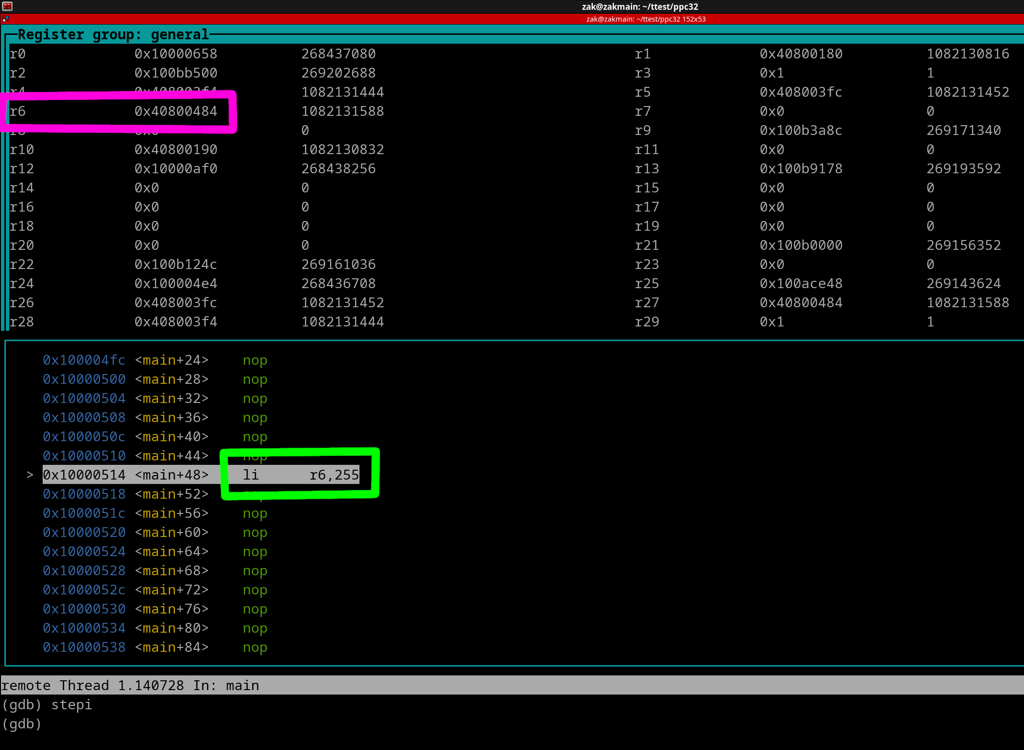
r6 is outlined in magenta. The li instruction is outlined in green. Now here's a pic of once the instruction has executed.
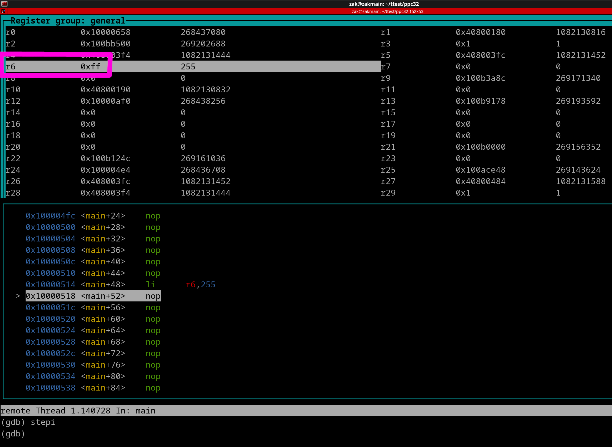
You can see that r6 is now 0xFF. Since the li instruction uses SIMM, you can instantly load any value of 0xFFFF8000 thru 0x7FFF into a register with just one li instruction. The next chapter will teach you how to write *ANY* value to a register. Let's continue with some more simple instructions...
PowerPC also includes typical divide and multiply instructions. There are only 2 divide instructions, they are as follows....
divw rD, rA, rB #Signed Division. rD = rA / rB
divwu rD, rA, rB #Unsigned Division. rD = rA / rB
NOTE: If a division by zero occurs, then the result is always 0.
NOTE: If a result is fractional, then standard rounding is applied (5.7 rounds to 6)
Here are a couple of basic multiply instructions...
mulli rD, rA, SIMM #Signed multiplication. rD = rA * SIMM
mullw rD, rA, rB #Signed multiplication. rD = rA * rB
As you can see, there is a Signed Divide Instruction vs an Unsigned Divide Instruction. Let's cover each instruction using the same example values. Assume that...
r4 = 0xFFFFFFFC
r6 = 0x00000002
..and we have this instruction...
diww r8, r4, r6
This will do a SIGNED division of r4 divided by r6, and the result being written to r8. Because this instruction treats its values as SIGNED, r4 will be treated as -4.
Let's run the division now. Negative 4 divided by 2 is negative 2.
r8 result = 0xFFFFFFFE (-2)
Now let's redo the example but use..
divwu r8, r4, r6
This will do an UNSIGNED division. Because this instruction treats its values as UNSIGNED, r4 will be treated as 4,294,967,294. Run the division...
r8 result = 0x7FFFFFFF (2,147,483,647)
Regarding the above multiply instructions, if the result exceeds 32-bits in width, then only the lower 32-bits of the result are written to rD. For example, if we have the following instruction...
mullw r10, r11, r12
With r11 = 0x7FFFFFFF, and r12 = 0x00007FFF. When the instruction executes, the "full" result of 0x3FFF7FFF8001 will have its width chopped down to 0x7FFF8001, and that final value will be written to r10.
Now let's cover another basic instruction...
Negate:
neg rD, rA
This will simply flip a positive number to be negative or vice-versa. Instances of zero remain as zero.
Example:
neg r5, r9
Pretend r9 is the value of 3 before the instruction has executed, what's in r5 isn't a concern because it's value will be overwritten once the instruction gets executed. The following pic shows us the state of the two registers right before the neg instruction is going to be executed...
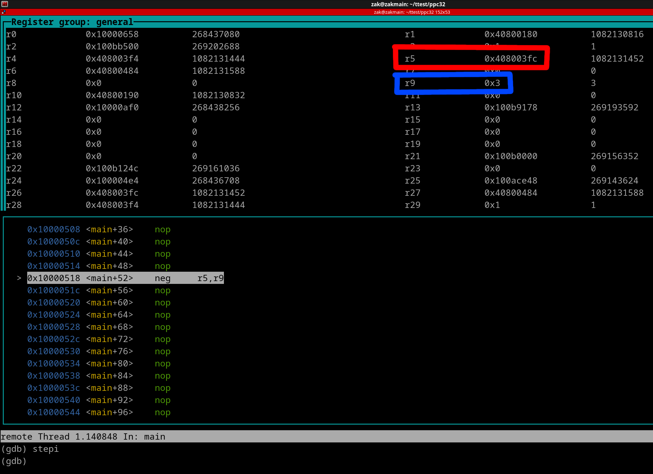
Source Register (r9) is outlined in blue and Destination Register (r5) is red. Let's execute the instruction...
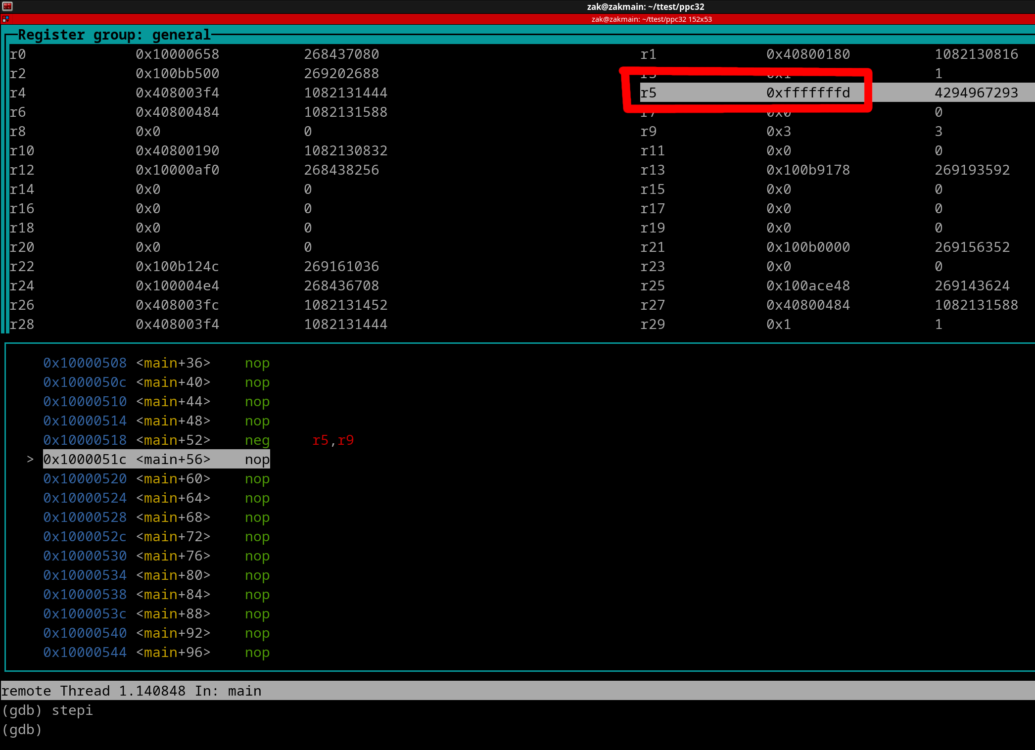
The neg instruction has resulted in r5 being -3.
Finally let's cover just one more easy/basic instruction.
Move Register:
mr rD, rA
This will simply copy rA's entire value into rD. Whatever was in rD beforehand is now overwritten.
Example:
mr r14, r28
Pretend r28 is the value of 0x00007FFC before the mr instruction executes. Once the mr instruction has been executed, r14 is now 0x00007FFC regardless of what was in it beforehand.
About General Instruction flow; writing multiple Instructions in your Source File:
Instructions (except in the case of exceptions and branches) execute in a top to bottom fashion. For example we have the following 3 instructions...
add r3, r10, r5 #This instruction will execute first
li r7, -1 #This instruction executes second
mullw r8, r8, r11 #And this instruction executes third
When writing instructions out in any Assembler, only one instruction can be present per 'line/row' in your Source File.