Chapter 24: The Stack
Now that you know how to call functions, we need to go over pushing and popping stack frames. That way you can write out your own functions and begin writing out your own Full Programs. This will also teach you how function prologues and epilogues work "underneath the hood". You will know what the Stack is, how it works, how to write your own Prologues+Epilogues, and other things.
Prologues of functions include instruction(s) for what is called "pushing the stack". Epilogues include instruction(s) for what is called "popping the stack".
Pushing the stack means to create a new stack frame. What is a stack frame? Well let's explain 3 important elements in the order shown below.
The SP register holds the Memory Address (pointer) that points to the very top of the Stack. The Stack contains what is called Stack Frames. At the very very top of the Stack is the newest/latest Stack Frame. Therefore SP always points to the latest (current) Stack Frame.
The Stack Frame is an area of memory within the Stack that holds values of registers, plus other data, that needs to be preserved throughout function call(s). A majority of contents within a Stack Frame are previous/saved values of the Callee-Saved Registers (r14 thru r31).
When a new stack frame is created, the Stack itself grows toward LOWER memory addresses. Visually speaking (on a memory viewer tool) a new frame is created on top of the current frame. Thus each new stack frame has a decreased memory address in comparison to the previous stack frame. Visually speaking, the Stack grows upward.
Four General Rules:
The layout format of Stack Frames slightly varies between which Assembler you intend to use. However, generally speaking, this is the most accepted/universal Stack format for PowerPC...
| Offset to SP | Item |
|---|---|
| 0 | Ptr to previous Stack Frame (Old SP) |
| 0x4 | Reserved for *next* Function's LR Address |
| 0x8 | Buffer Space for possible future Function Input |
| 0x8+ | Called Saved Registers |
| 0x8+ | Caller Saved Temp Registers |
| 0x8+ | Alignment Space if necessary |
NOTE: Some items may not be used, hence why many items have the offset of 0x8
Pay close attention to the item that stores at offset 0x4. It's for the NEXT function's LR. That means when a function gets called, it's LR value (return address) gets placed into the **previous** (older) frame. This is a huge quirk with PowerPC unfortunately.
The item at offset 0 allows for what is called back-tracing. It's for Debugger programs so they can look back at all the previous frames in chronological order. Those who specialize in debugging may write programs that can generate exception reports that includes a back-trace of the past 5 Stack Frame Pointers.
In order to know how to properly create a new Frame, we will go over the most simple Function Prologue. It will create the bare minimum 16-byte Stack Frame. For the following example, SP starts off with the value/address of 0x80399800
Example:
stwu sp, -0x0010 (sp)
mflr r0
stw r0, 0x0014 (sp)
What occurs~
Remember that I said earlier that the Stack grows towards LOWER addresses. In a visual sense, on a memory viewer tool, this means new frames are created on TOP of the older frames.
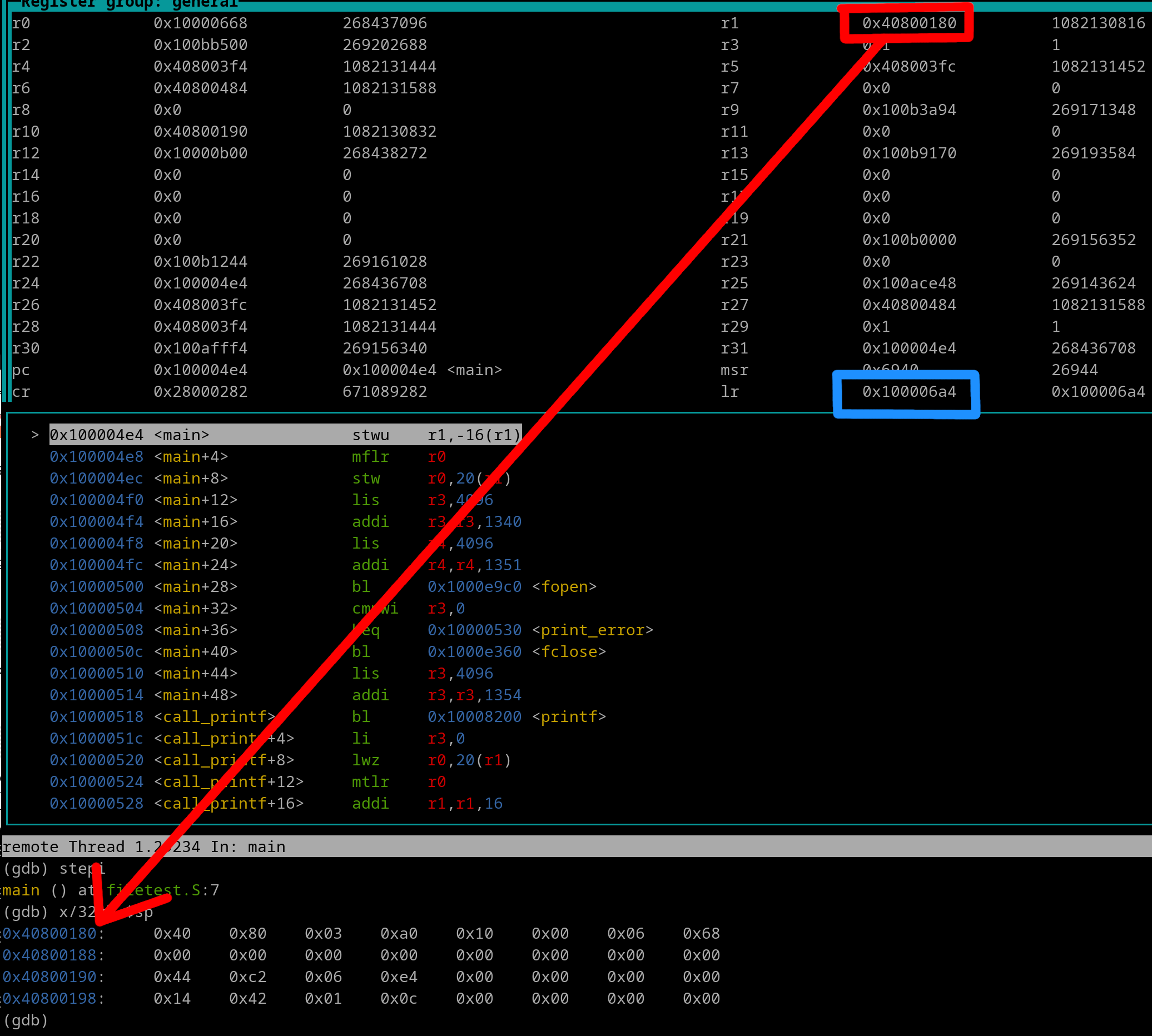
Let's view the above code in GDB. We are at the first instruction of the prologue but have NOT yet executed it...

We see that..
SP = 0x40800180 (not been modified by the prologue yet)
LR = 0x100006A4 (NOTE that the LR contains the address that will return back to the Caller/Parent)
Now lets execute the stwu instruction...
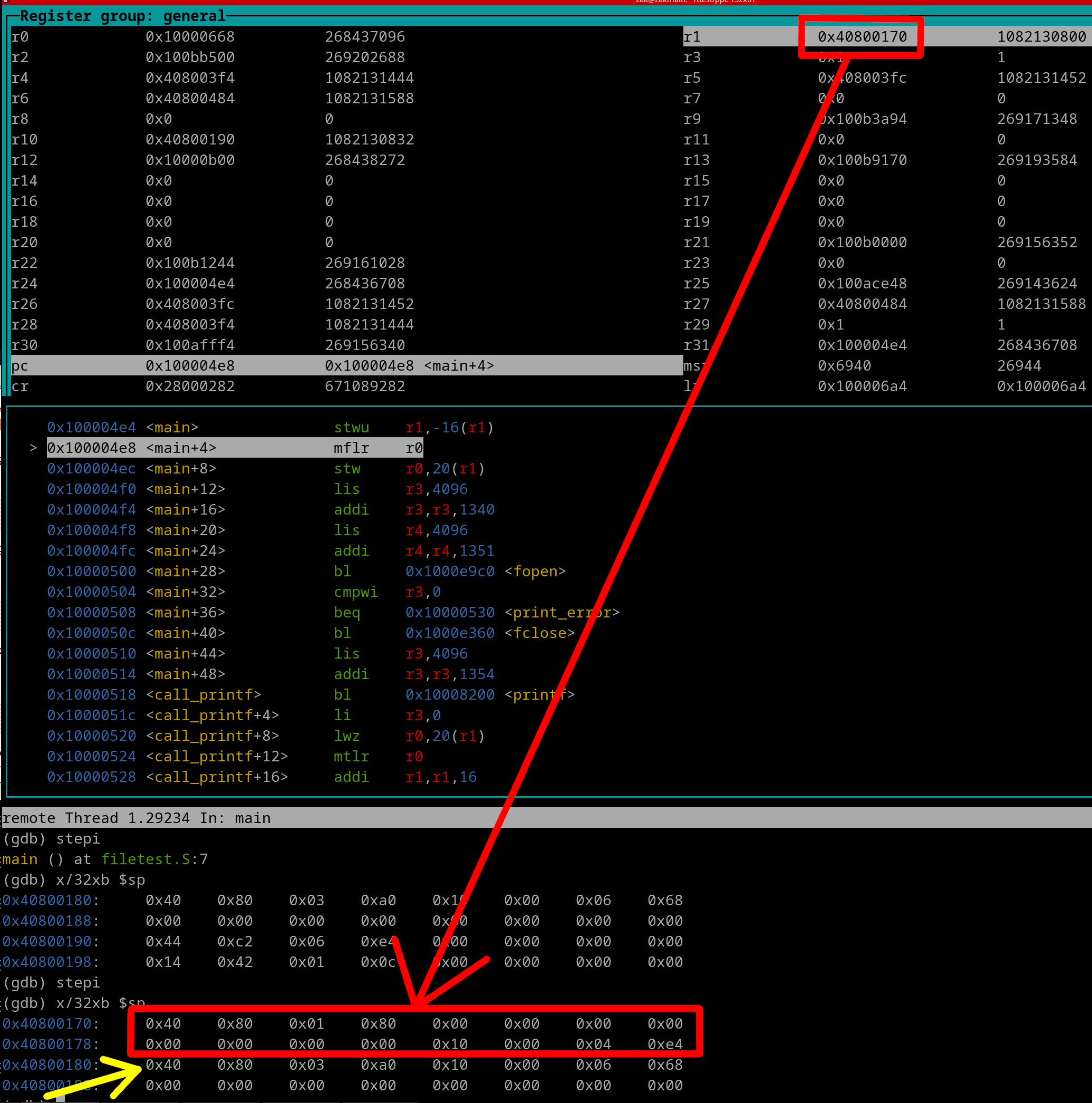
We that...
SP = 0x40800170
LR = 0x100006A4
SP has been decremented by 0x10 (new frame created). The new frame is outlined in red. The yellow arrow is pointing to the start of the now-old frame. Let's execute the mflr instruction now...
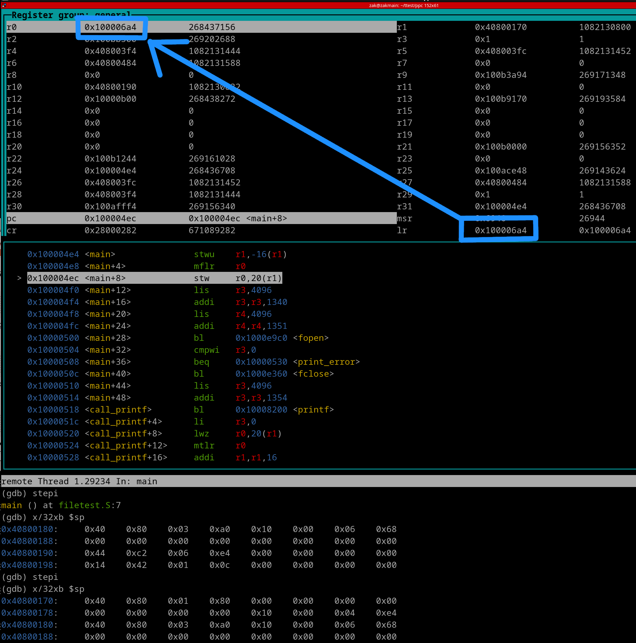
The LR value now is sitting in r0. Let's execute the stw instruction now...
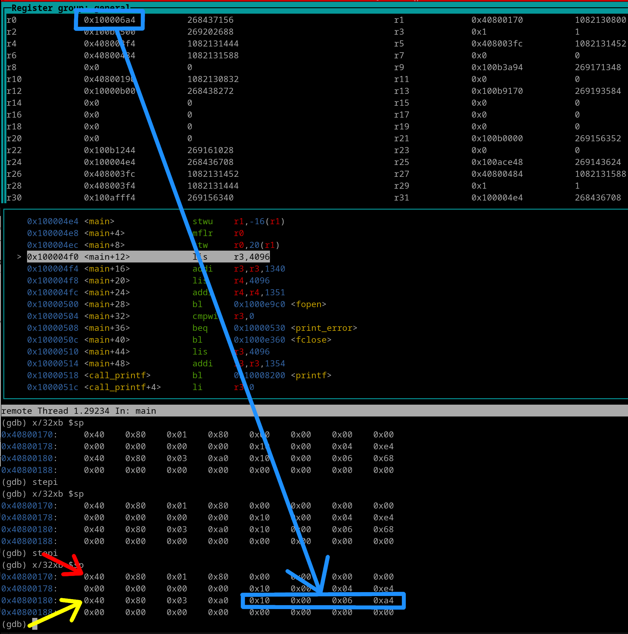
As you can see the LR (function return address) was placed in its reserved spot in the PREVIOUS frame! Red arrow points to the current frame. Yellow arrow points to the old frame. Sweet, we just stepped thru an entire prologue.
Alright moving onto the epilogue. The epilogue that will work with our prologue is the following...
lwz r0, 0x0014 (sp)
mtlr r0
addi sp, sp, 0x10
blr
What occurs~
Let's step thru it in GDB. Here's a pic of right before the lwz has executed
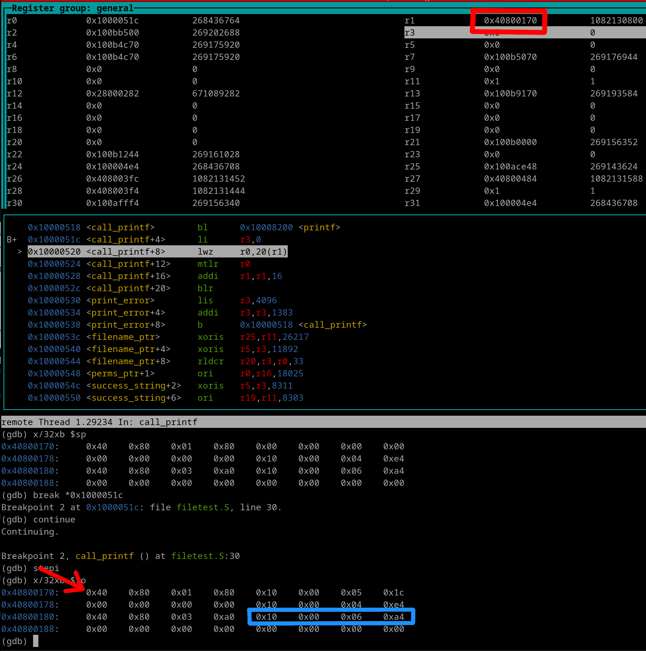
Now let's execute the lwz instruction
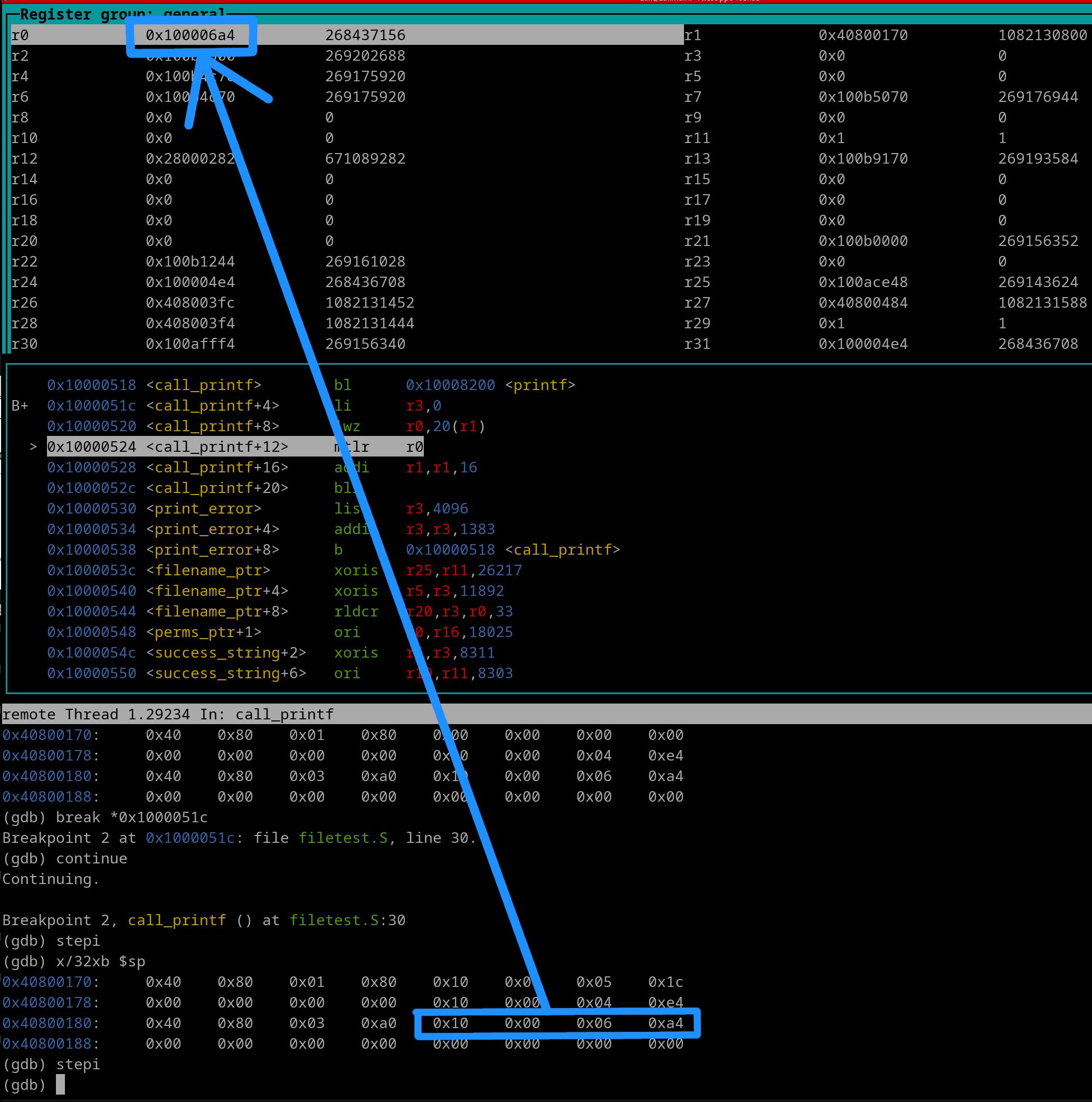
We see the function return address is sitting in r0. Alright, executing the mtlr instruction now..
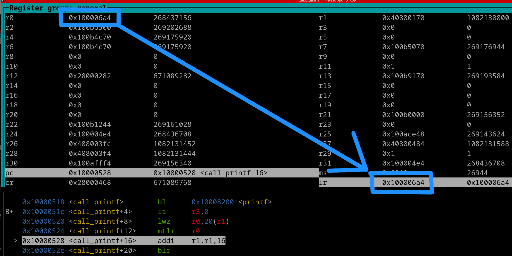
Obviously, the mtlr instruction copies the return address from r0 to the LR. Let's execute the addi instruction now...
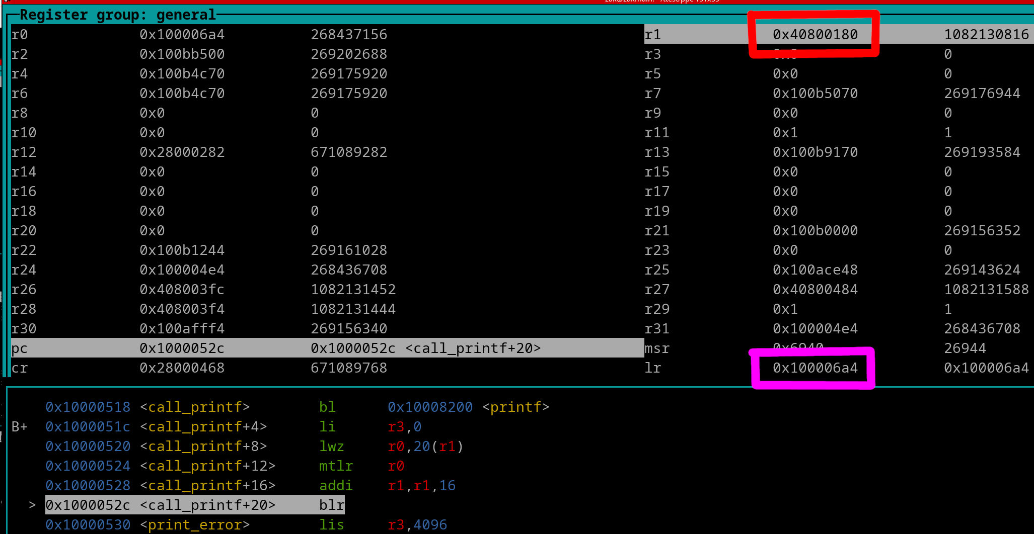
We see that..
SP = 0x40800180 (is now back to its previous/old value)
LR = 0x100006A4
The function is now ready to end. Let's execute the blr instruction.
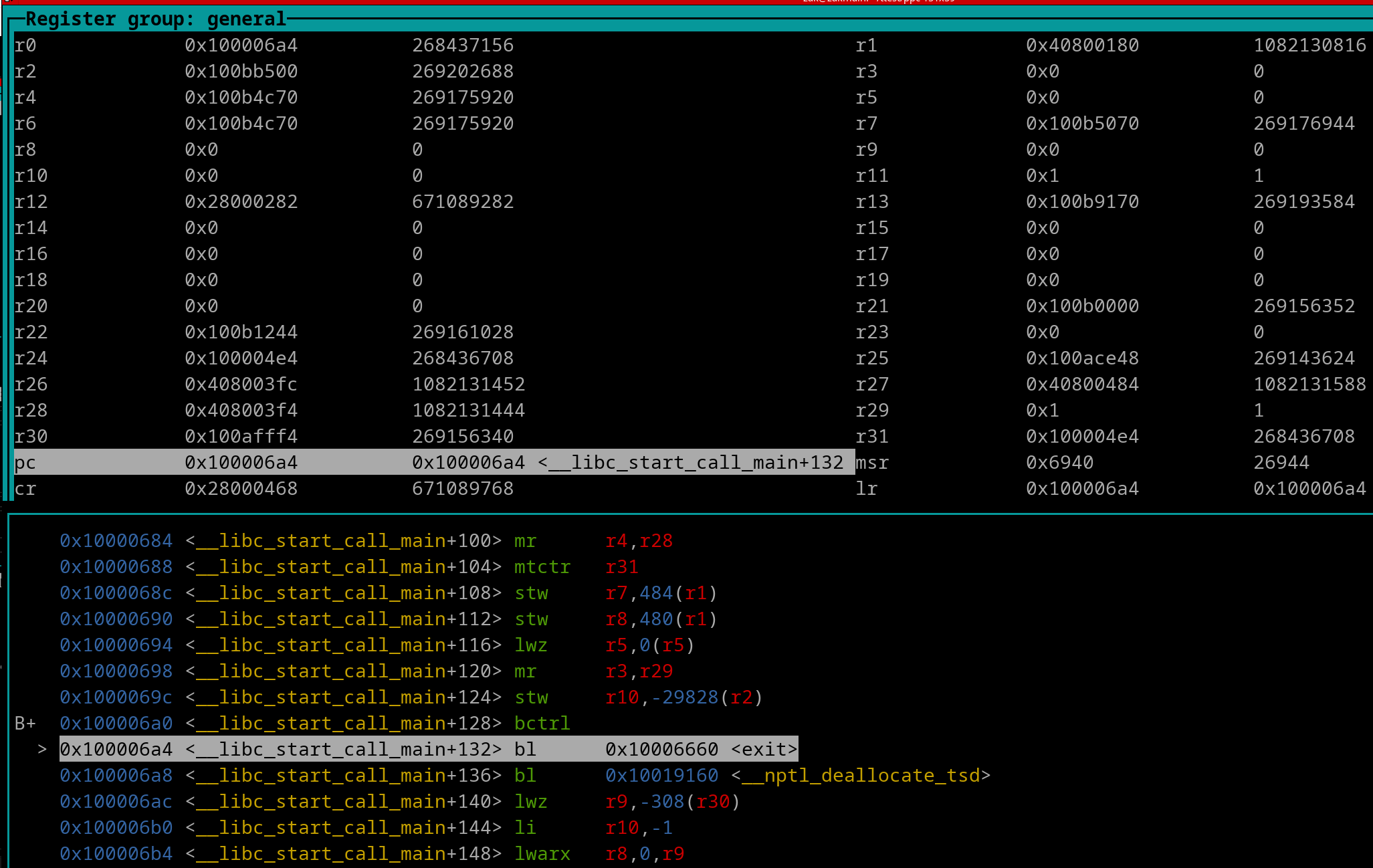
And we are now at the function's Caller.
Back-tracing is important to learn because you may end up using PowerPC emulators (other than QEMU+GDB) that may show a Back-Trace table that list previous function call or return addresses. Here's a picture at a random spot in a program....
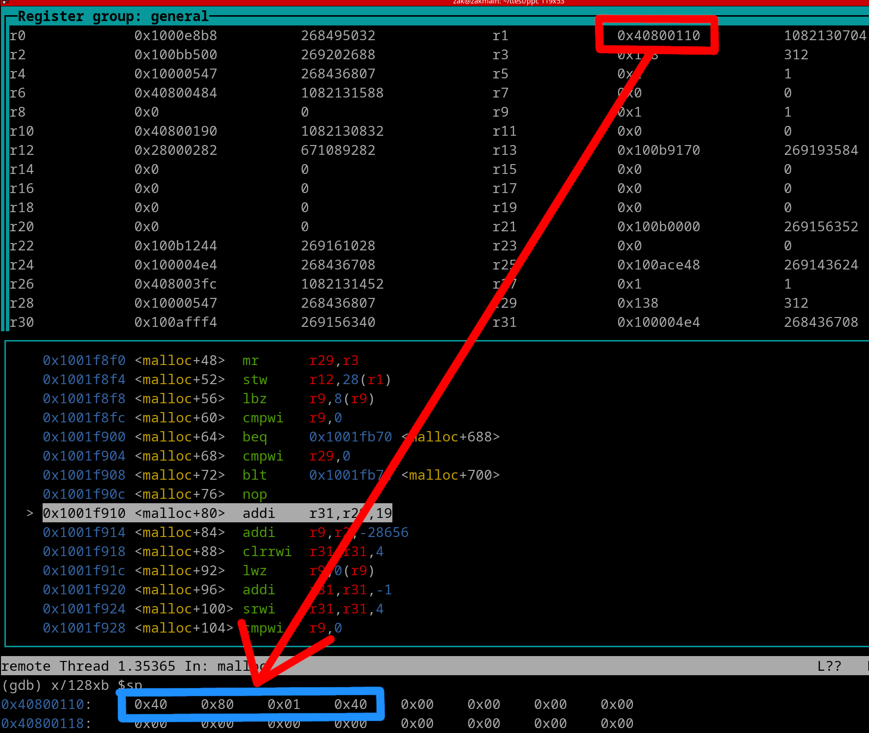
We see SP (outlined in red) points to the top of the stack (0x40800110; newest/current frame). Now the first item located in this current frame is the pointer to the previous frame (0x40800140; outlined in blue). This is the old SP (what SP was before the most recent prologue). What we can do is take the value of older SP minus newer SP. This will give you the size of the frame. 0x40800140 - 0x40800110 = 0x30 (48 bytes; size of current frame). You can use this method to calculate the size of any frame within the Stack.
Let's take a wider view of memory starting at SP/0x40800110....
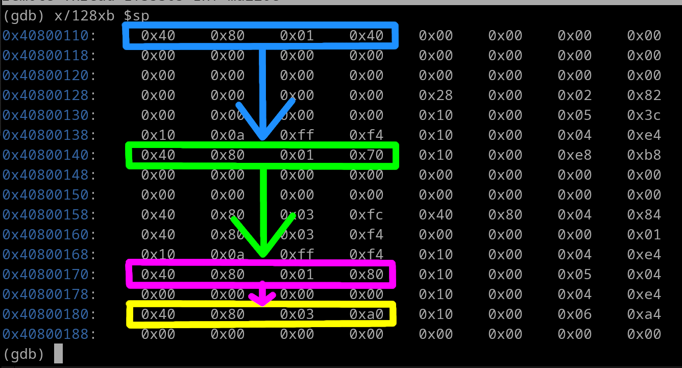
The blue outline is the pointer to the previous frame (old SP; 0x40800140). What we can do is use that pointer to jump to the next elder frame which is outlined in green (0x40800170). We can then jump to that pointer to go back even further. This will make us arrive at the pointer outlined in magenta (0x40800180). Go back even further and we arrive at the yellow outlined pointer (0x408003A0). To keep going back, we need to view the memory at 0x408003A0...
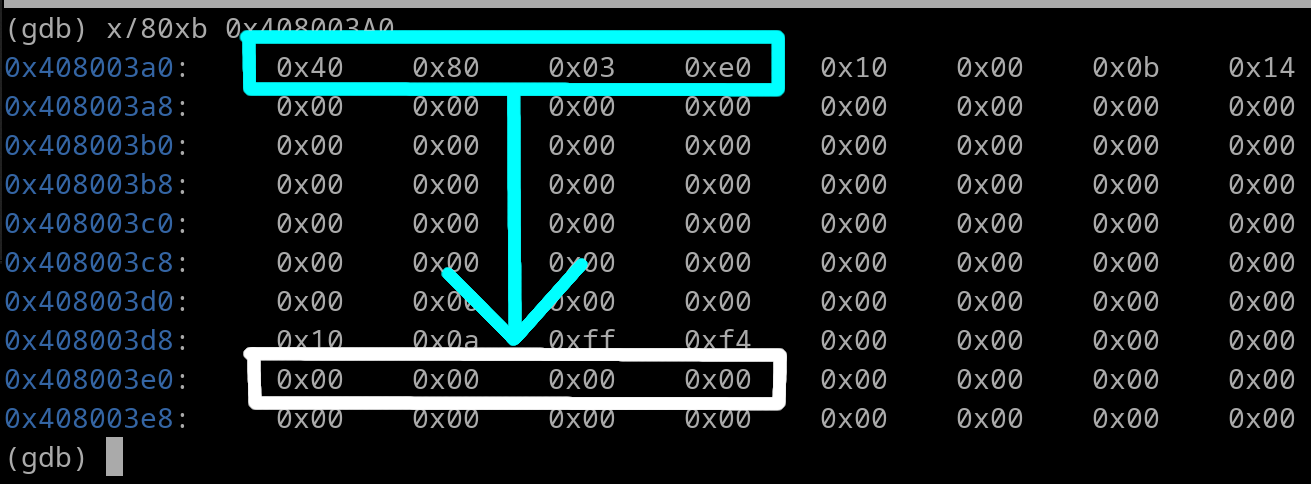
We see a new pointer outlined in cyan which is 0x408003E0. Now what do we see at 0x408003E0? We see a NULL Pointer (outlined in white). What does this mean? Well it means we have reached the very bottom/end of the entire Stack. We can't backtrace any further. As an fyi, an "all-1's" pointer (0xFFFFFFFF) may be present instead of a null pointer. This still means the same thing, you've reached the end of the Stack.
Usually the Stack isn't this small. Backtracing/debugging programs usually only display/print the past 5 frames.
Function(s) can preserve data by storing it inside a Stack Frame. Since the amount of data that needs to be preserved will vary, you will see different types of prologues and epilogues. We'll learn how to create our own custom size stack frames.
This is a simple formula for calculating Stack Frame size when GPRs are the *ONLY* item in question for storing onto the Frame
A function may need to backup registers in order to get itself some free registers to use for a task. When such a scenario occurs, the callee saved registers are the first to be saved. If a callee-saved register needs to be saved, the first one to be used is r31. If a function needs more, it will work its way down the register list til r14, the final callee-saved register.
For example, let's say a function will want to use 3 registers to keep some new data intact thru a child function that it contains. The Stack Frame required size is determined as such...
The Frame size will be 32, or 0x20 in hex. The prologue will be this...
stwu sp, -0x0020 (sp)
mflr r0
stmw r29, 0x8 (sp)
stw r0, 0x0024 (sp)
With this prologue, let's view what the Stack Frame layout would look like....
| SP Offset | Item |
|---|---|
| 0 | Old SP |
| 0x4 | Reserved for *next* Function's LR Address |
| 0x8 | r29 |
| 0xC | r30 |
| 0x10 | r31 |
| 0x14 thru 0x1F | Space for Alignment |
The epilogue for the above prologue would be this...
lwz r0, 0x0024 (sp)
lmw r29, 0x8 (sp)
mtlr r0
addi sp, sp, 0x0020
blr
Ok, let's step it up a bit. Say we have a function that needs to backup 5 GPRs. Calculate the Frame size...
Frame size will be 48 bytes in size (0x30 in hex). The prologue will be this...
stwu sp, -0x0030 (sp)
mflr r0
stmw r22, 0x8 (sp)
stw r0, 0x0034 (sp)
Here's the Stack Frame layout once the prologue has been completed
| SP Offset | Item |
|---|---|
| 0 | Old SP |
| 0x4 | Reserved for *next* Function's LR Address |
| 0x8 | r22 |
| 0xC | r23 |
| 0x10 | r24 |
| 0x14 | r25 |
| 0x18 | r26 |
| 0x1C | r27 |
| 0x20 | r28 |
| 0x24 | r29 |
| 0x28 | r30 |
| 0x2C | r31 |
As you can see, no space for alignment was necessary. Now here's the epilogue...
lwz r0, 0x0034 (sp)
lmw r22, 0x8 (sp)
mtlr r0
addi sp, sp, 0x0030
blr
Factoring in FPRs, lets update our equation for calculating stack frame size
Floats must ALWAYS be preserved in the stack as double precision. For a prologue of 2 GPRs and 1 FPR, we need a Frame size of 32 (0x20) bytes.
stwu sp, -0x0030 (sp)
mflr r0
stmw r30, 0x8 (sp)
stfd f31, 0x10 (sp)
stw r0, 0x0034 (sp)
Frame layout after prologue:
| SP Offset | Item |
|---|---|
| 0 | Old SP |
| 0x4 | Reserved for *next* Function's LR Address |
| 0x8 | r30 |
| 0xC | r31 |
| 0x10 | f31 |
| 0x18 thru 0x1F | Space for Alignment |
..and here's the epilogue
lwz r0, 0x0034 (sp)
lmw r30, 0x8 (sp)
lfd f31, 0x10 (sp)
mtlr r0
addi sp, sp, 0x0030
blr
There may be times a function will allocate extra memory for buffer(s) of a child function.
Some functions may require an Argument to be a Pointer to write some output information to. This is known as an Output Buffer. A function may require an Argument to be a Pointer that points to a small size of memory. The contents in that small segment of memory will be processed by a Function to do a task. This is known as an Input Buffer.
Buffer Space typically goes first (after old SP and next Func LR) in the PowerPC Stack Frame layout. Let's say we need to allocate 98 bytes of buffer space in a Prologue and nothing else. The Stack Frame would need to be 128 (0x80) bytes in size. The prologue would be this....
stwu sp, -0x0080 (sp)
mflr r0
stw r0, 0x0084 (sp)
The stack frame size is 128 bytes in size because....
16 (for fp and lr) + 98 (buffer) = 114
114 must be rounded up to 128 (0x80 in hex) to be divisible by 16
The stack frame's layout after the Prologue is this...
| SP Offset | Item |
|---|---|
| 0 | Old SP |
| 0x4 | Reserved for *next* Function's LR Address |
| 0x8 thru 0x71 | 98 bytes of Buffer space |
| 0x72 thru 0x7F | Space for Alignment |
The corresponding epilogue is this...
lwz r0, 0x0084 (sp)
mtlr r0
addi sp, sp, 0x0080
blr
Here's a prologue and epilogue for 3 GPRs, 2 FPRs, and 48 bytes (0x30) of buffer space
Frame size is 96 bytes (rounded up from 84) ---- {(3 x 4) + (2 x 8) + 48 + 8}
#Prologue
stwu sp, -0x0060 (sp)
mflr r0
stmw r29, 0x38 (sp)
stfd f30, 0x44 (sp)
stfd f31, 0x4C (sp)
stw r0, 0x0064 (sp)
| SP Offset | Item |
|---|---|
| 0 | Old SP |
| 0x4 | Reserved for *next* Function's LR Address |
| 0x8 thru 0x37 | 48 bytes of Buffer space |
| 0x38 | r29 |
| 0x3C | r30 |
| 0x40 | r31 |
| 0x44 | f30 |
| 0x4C | f31 |
| 0x54 thru 0x5F | Space for Alignment |
#Epilogue
lwz r0, 0x0064 (sp)
lfd f30, 0x4C (sp)
lfd f31, 0x44 (sp)
lmw r29, 0x38 (sp)
mtlr r0
addi sp, sp, 0x0060
blr