Chapter 16: Condition Register, Carry & Borrow
This chapter will teach you about the Condition Register, and how to add & subtract values that exceed 32-bits in width.
Back in Chapter 11 you've learned about Compare & Branch instructions. So far, they may seem like black magic in how they truly work. What occurs is that the Compare instruction sets certain bits in the Condition Register (CR) based on the result of the comparison.
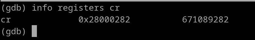
The Condition Register is a SPR that contains 8 fields. Field 0 (cr0) thru Field 7 (cr7). For GDB, you can view the contents of the CR with the following command...
info registers ctr
Example picture:
CR breakdown:
STUVWXYZ
S = cr0
T = cr1
U = cr2
.. ..
Z = cr7.
Each field is 4 bits in width (1 digit). A standard compare instruction such as...
cmpwi r0, 100
..will utilize cr0. This is because that instruction is actually a simplified mnemonic for this...
cmpwi cr0, r0, 100
If you wish to use cr7 instead of cr0, you would write the instruction like this...
cmpwi cr7, r0, 100 #Notice the inclusion of "cr7"
Understand that if you omit the CR field, the Assembler will default to using cr0.
An important thing to keep in mind is that if you didn't use cr0 for a compare instruction, you must designate the CR field in the subsequent branch instruction. Like this...
cmpwi cr7, r0, 100
beq cr7, somewhere
Each CR field has 4 bits of data that use the following structure.
Here is a table breaking down the entire Condition Register
| LT | GT | EQ | SO | crX |
|---|---|---|---|---|
| 0 | 1 | 2 | 3 | cr0 |
| 4 | 5 | 6 | 7 | cr1 |
| 8 | 9 | 10 | 11 | cr2 |
| 12 | 13 | 14 | 15 | cr3 |
| 16 | 17 | 18 | 19 | cr4 |
| 20 | 21 | 22 | 23 | cr5 |
| 24 | 25 | 26 | 27 | cr6 |
| 28 | 29 | 30 | 31 | cr7 |
Whenever a bit in the crF is high, the condition was true FROM THE MOST RECENT comparison instruction. Whenever a bit was low, the condition was false FROM THE MOST RECENT comparison instruction.
Multiple bits can be set high and/or low from a comparison instruction. Now that you understand the crF bits, let's go over what branch instructions actually do.
Example:
bge- cr7, some_label #checks LT bit of cr7. If low, branch is taken.
Now that you understand the CR, there are instructions that allow you to modify it on the fly. These instructions are rare and they are "slow" (not ideal for fast programs), but let's go over them so you have an idea of what they do if you run into them "in the wild". Here are the two instructions available for moving data to/from the CR directly.
mtcr rD #This will copy rD's value to the CR. The entire CR value that was there beforehand is overwritten.
mfcr rD #This will copy CR's value to rD. Whatever was in rD beforehand is now overwritten.
Now we can dive into some actual CR Operation-type instructions. However, let's go over some important symbols that will make it easier for both of us in the future chapters. Up to this point, we have been using "plain English" to describe Logical Operations. For example, I would use the term "Logical AND" for saying Logical AND in the literal sense. Many code developers won't use such terms, or their notes won't be written in such a fashion. They will use common symbols to "speak" in Logical Operations. You need to get familiar with these symbols so you can read other people's work easier. Here they are..
If you are familiar with C/C++, some of these are for Binary Logical Operations. Which holds true since Logical Operations at the Assembly Level is always Binary-based.
Here are instructions where you can manipulate exact bits within the CR. The following instructions use a operand labeled as "crb". crb = the exact bit within the CR. So for example, a crb value of 2 would be bit 2 of the CR, which would be the cr0 EQ bit.
crand crbD, crbA, crbB #crbD = crbA & crbB
crandc crbD, crbA, crbB #crbD = crbA & (!crbB)
creqv crbD, crbA, crbB #crbD = ~(crbA ^ crbB)
crnand crbD, crbA, crbB #crbD = ~(crbA & crbB)
crnor crbD, crbA, crbB #crbD = ~(crbA | crbB)
cror crbD, crbA, crbB #crbD = crbA | crbB
crorc crbD, crbA, crbB #crbD = crbA | (!crbB)
crxor crbD, crbA, crbB #crbD = crbA ^ crbB
Let's look at an example--
crand 2, 26, 30
The above will do the following--
CR Bit 26 is the cr6 EQ bit and CR bit 30 is the cr7 EQ bit. Result is placed in cr0's EQ bit. Instead of writing the CR's "raw" bit value in a CR-Operation Instruction, we can use this template below..
crb = 4*crX+zz
X = Which CR Field to use (0 thru 7)
zz = lt, gt, eq, or so (the CR bit name scheme)
Thus, we can write the earlier crand instruction like so....
crand 4*cr0+eq, 4*cr6+eq, 4*cr7+eq
As mentioned earlier, these CR-Operation Instructions are uncommon plus they are slow. I was planning on writing out some examples of CR-Operations in actual code, but all it would do is confuse the average reader. In fact, these CR-Operation Instructions are so bad/slow, that other more modern architectures such as the ARM64 Assembly (what's in your modern cell phone), don't even have these type of instructions. Also, you won't find these CR-Op instructions that often "in the wild". Compilers (tools that transform something such as C to Assembly) won't use them due to reasons mentioned earlier, except for some cases for floating point comparisons. Enough blabber about CR-Ops, let's move on.
Back in Section 2, you've learned about the four flags in a Condition Register field. LT, GT, EQ, and SO.
The SO flag is unique, it is a copy of the SO bit of the XER register. The XER (Fixed Point Exception) Register is a Special Purpose Register that contains a few bits of information.
You can view the XER register anytime within GDB using the following command...
info registers xer
XER bit breakdown:
Some of the above info may go right over your head, that's okay. What we need to focus on is bit 2 and nothing else. The Carry bit. This bit will allow use to implement Carry or Borrow.
The CA flag is needed for adding/subtracting numbers that exceed 32 bits in width.
For addition operations, the Carry Flag gets set if the result exceeded 0xFFFFFFFF. If not, the flag gets cleared. For subtraction operations, the Carry Flag gets set if the result is 0 or higher. Otherwise, the flag gets cleared.
There are four instructions that we will go over that set/clear CA bit. Those are...
Knowing this allows us to implement something such as 32-bit addition that is capable of working with 64-bit results. Obviously, there are no 64-bit sized GPRs, so we will need our result to use a pair of GPRs. Here's a snippet of code that has the 64-bit input in r3 and r4. It will be added with a 32-bit 2nd input value that's in r5. The result will be placed back into r3 and r4. r3 holds the upper 32-bits, r4 holds lower 32-bits...
addc r4, r4, r5
adde r3, r3, r0
The first instruction (Add Carrying) is to add up the lower 32-bits (r4) of the current number to the 32-bit adder (r5). The CA flag of XER need to be set for Carry to work, hence why "c" is appended in the add instruction (addc). Therefore if a situation arises where something such as 0xFFFFFFFE + 0xB occurs, the Carry will be set.
The second instruction is called "Add Extended". The instruction can only use two source registers, no Immediate Value usage allowed. Well this is a problem because we only need to add r3 with XER[CA]. Lucky for us that in the adde instruction, if r0 is a source register, it is treated as literal zero. Therefore we can plug in r0 as the 2nd source register, and it won't change the result of the adde. instruction. The adde instruction does the following...
r3 = r3 + literal 0 + Carry Flag
To show how the above snippet of code works, let's plug some numbers into it.
Before code is executed...
r3 = 0x00000000
r4 = 0xFFFFFFFE
r5 = 0x0000000B
The first instruction (addc) will add r4 and r5 together. The result is 0x00000009. The Carry Flag of XER is set since the result exceeded 0xFFFFFFFF. XER[CA] is now 1. When the 2nd instruction (adde) gets executed, the following 3-value addition is performed...
0 + 0 + 1
The first 0 is what was in r3. The second 0 is the literal zero due to using r0. The 1 is the Carry Flag. The result of this entire addition is 1 and is placed back into r3. Thus r3 is now 0x00000001. Now "connect" r3 with r4 for a 64-bit value, and you have... 0x0000000100000009. As you can see, the addition was performed correctly and we have our 64-bit result.
---
Let's quickly go over a subtraction example. 64-bit current input (r3 & r4) that will use 32-bit subtraction (r4 - r5). Here's the code..
subc r4, r4, r5 #Perform the 32-bit subtraction, update Carry Flag. If a borrow occurs, Carry Flag will be cleared. If not, it will be set high.
subfe r3, r0, r3 #r3 = !literalzero + 2 + XER[CA]
Let's plug in some numbers to show this snippet of code works.
Before code is executed..
r3 = 0x0000000000000002
r4 = 0x0000000000000001
r5 = 0x0000000000000003
The subc (Subtract Carrying) will do..
0x00000001 - 0x00000003 = 0xFFFFFFFE.
Then the subfe (Subtract From Extended) instruction will do...
0xFFFFFFFF + 0x00000002 + 0 = 0x00000001
The 0xFFFFFFFF is the logical NOT'd value of literal zero due to r0 usage. The middle 2 is what was in r3. The zero is the CA flag of XER. It is 0 because it was cleared since the subtraction result (from subc) went below 0, a borrow occurred.
Now if we "connect" the r3 with r4, we will have our 64-bit final result...
0x00000001FFFFFFFE
Voila it works. You can use the following template for 64-bit addition (adding with a 32-bit value)
rX = upper 32 bits of result
rY = lower 32 bits of result
rZ = 32-bit value to add by
addc rY, rY, rZ
adde rX, rX, r0
And use this template for 64-bit subtraction (subtracting with a 32-bit value)
rX = upper 32 bits of result
rY = lower 32 bits of result
rZ = 32-bit value to add by
subc rY, rY, rZ
subfe rX, r0, rX
Onto the next chapter!