Chapter 7: Basic Instructions
We can finally get into some actual Assembly instructions. This will be a pretty hefty chapter. There is a lot to unpack. Please take your time. A great first instruction to learn would be the add instruction.
Add:
add xD, xA, xB
add wD, wA, wB
The add instruction has two "versions". One for extended register use and one for non-extended use. Many basic instructions will have this feature of being equipped with two versions.
We'll focus on the extended version of add. In the add instruction, the value in xA is added with the value in xB. The result of this addition is placed into xD. Whatever value that was in xD beforehand, is overwritten.
Example add instruction:
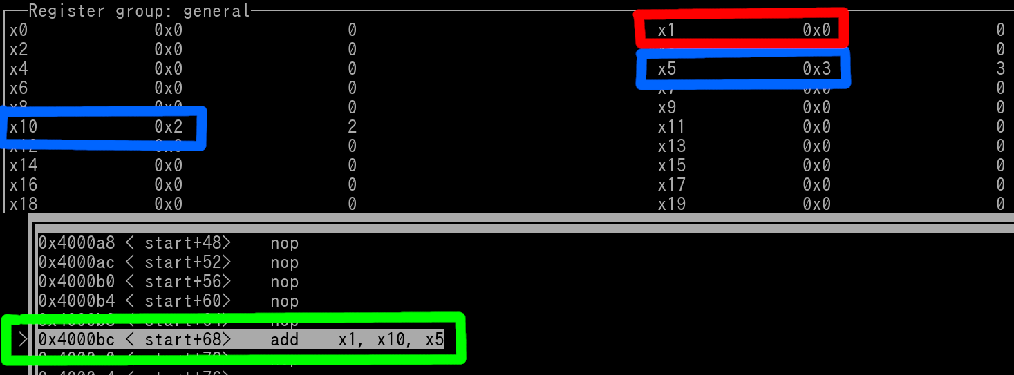
add x1, x10, x5
Value in x10 is added with value in x5. Result placed in x1.
Let's pretend that before the instruction has executed, x10 = 2, and x5 = 3. What's currently in x1 is not a concern for us, as it will be overwritten once the instruction has executed.
The picture below shows you an instance of this instruction right before it is executed. Both Source registers are outlined in blue, and the Destination Register is outlined in red. The add instruction is outlined in green.
Some things to unpack from the above Pic:
The above is a screenshot from a tool called GNU-Debugger. I'm using this tool with custom made Assembly Programs/Code to use for various instruction examples. You will using this exact tool in the far future of this Tutorial. All registers are displayed in their Extended form. Each register will have it's Hex and Decimal equivalent values listed. You can see the Hex values are on the near right for each corresponding Register, while the Decimal equivalents are on the far right. Another thing to keep in mind is that the Decimal equivalents are always 64-bit Signed Decimal equivalents. This is a quirk of the Debugger that can't be changed/modified. Finally let's discuss the instruction outlined in green. You will see some information to the left of the instruction. The Hex Value that's incrementing by 4 is the Program Counter. The "start+68" is simply a reference point to in regards to the start of the Program. We'll discuss the nop instructions shortly.
Anyway, once the instruction gets executed the addition of 2+3 will be performed. The result of 5 is placed into x1. View the following picture...
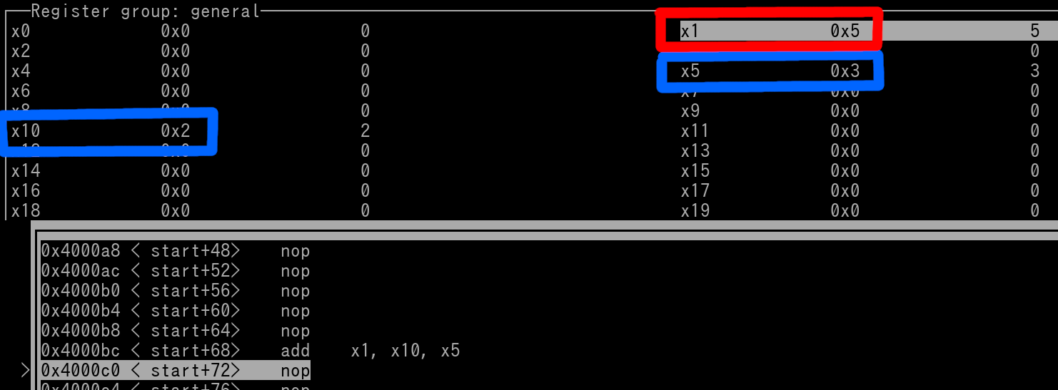
The result of 5 being placed in x1 is outlined in red.
Regarding the nop instruction, it simply tells the CPU to do nothing, literally. It can serve a variety of purposes. I'm simply inserting nop everywhere as having other unrelated possible complex instructions everywhere may be "visually cumbersome".
What's great about the ARM64 Assembly Language is that plenty of instructions have multiple formats. For example, in the add instruction, you can also use 1 source register with an Immediate Value. This is known as "Add Immediate".
Add Immediate:
add xD, xA, aimm
add wD, wA, aimm
What is aimm?
aimm stands for Arithmetic Immediate Value. It covers the following Immediate Value Types~
UIMM12 is your typical Unsigned 12-bit Immediate Value Range that you've learned about in Chapter 6. There's also a shift mechanism that can be implented to this to further increase the range, but that will be covered in Chapter 15.
UIMM24 is an Unsigned 24-bit Immediate Value Range but has many restrictions. We won't cover UIMM24 as it includes odd restrictions and is too complicated for a beginner to understand at this time.
NIMM25 is any number from (-2^24)-1 thru -1. In Hex form for a non-extended register, this is 0xFF000000 thru 0xFFFFFFFF. In Hex form for an extended register, this is 0xFFFFFFFFFF000000 thru 0xFFFFFFFFFFFFFFFF.
As a Beginner, don't get too caught up in the Immediate Value Ranges. Basically, use whatever value you need to. The Assembler will most likely be able to "alter" your instruction on the fly so it can be assembled. If you are running into too many errors of invalid Immediate Ranges when using the Assembler, then Chapter 8 will explain in detail on how to get around this issue.
Example of an Add Immediate Instruction:
add x15, x15, #0x1
IMPORTANT: As an fyi, there is no such thing as Signed vs Unsigned addition. The addition does not function in that 'manner'. For example: 0xFFFFFFF0 + 0x1 = 0xFFFFFFF1. 0xFFFFFFF1 will always be the result. There are indeed a some instructions that are Signed vs Unsigned specific, but don't fret as the naming of such varying instructions differ to let you known the Signage (i.e Signed Multiply vs Unsigned Multiply instructions). Finally, if an addition can't be represented by a proper value (Example: 0xFFFFFFFF + 0x2), then an item known as the Carry Flag will be set. This is discussed in Chapter 16. Fyi, 0xFFFFFFFF + 0x2 would result as 0x00000001 in a non-extended register.
IMPORTANT: For any ARM64 instruction where you use an Immediate Value, you *SHOULD* pre-pend said value with a hashtag (#) symbol. The reason being is that some Assemblers may enforce this rule. If it's not followed, the Assembler will refuse to Assemble your Source File. Lucky for us, the GNU Assembler you've installed earlier, is nice and allows you to omit the # symbol. "Official" ARM format requires you to have the value pre-pended with the #.
The value in x15 is added with 1. The result of this addition in rewritten back into x15. That is because the register used for the Destination Register is the same register used for the Source Register. Thus x15 will simply be incremented by 1. Let's pretend x15 was the value of 7 before the instruction was executed. View the following picture...
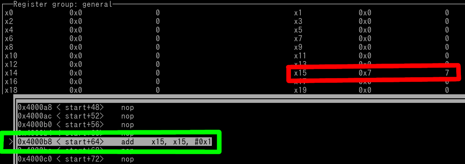
We can see x15 (outlined in red) is 7 but the add instruction (outlined in green) hasn't been executed yet. Now, when the add instruction does execute, x15 will be incremented by 1 as shown by the following picture...
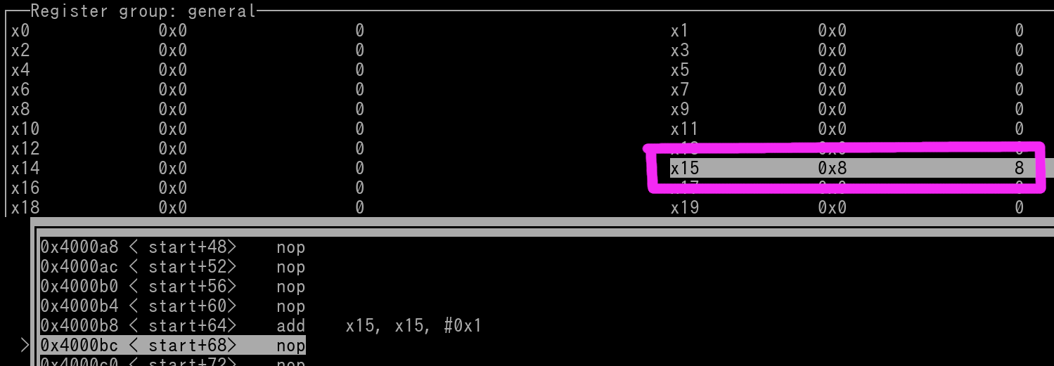
As you can see, x15 (outlined in magenta) has been incremented by 1 and now contains the value of 8.
Now that you have learned your first ever ARM64 instruction, we need to cover a small but significant topic. Back in Chapter 5 we quickly discussed about writing notes/comments in a Source File. Well, you can write these notes/comments adjacent to instructions. Like this...
add x15, x15, #1 // Increment x15 by 1
Subtract & Subtract Immediate:
sub xD, xA, xB //xD = xA - xB
sub wD, wA, wB //wD = wA - wB
sub xD, xA, aimm //xD = xA - aimm
sub wD, wA, aimm //wD = wA - aimm
Example sub immediate instruction:
sub x0, x25, 20 //Value in x25 minus 20 is preformed. Result is written to x0.
Alternatively, you could write the instruction as "sub x0, x25, 0x14" if you prefer to write the Immediate Value in Hex form.
ARM64 also includes typical divide and multiply instructions. There are only 4 divide instructions, they are as follows....
sdiv xD, xA, xB //Signed Division. xD = xA/ xB
sdiv wD, wA, wB //Signed Division. wD = wA / wB
udiv xD, xA, xB //Unsigned Division. xD = xA / xB
udiv wD, wA, wB //Unsigned Division. wD = wA / wB
NOTE: If a division by zero occurs, then the result is always 0.
NOTE: If a result is fractional, then standard rounding is applied (5.7 rounds to 6)
NOTE: There are no forms of the Divide instructions that permits Immediate Value implementation
Here is the most basic multiply instruction...
mul wD, wA, wB //Signed Multiplication. wA * wB = wD
mul xD, xA, xB //Signed Multiplication. xA * xB = xD
This will do a basic signed multiplication of the two source registers. The result is written to the Destination Register. If the result exceeds 32-bits (for non-extended use) or 64-bits (for extended use), then those lower 32/64-bits of the result is what is written to the Destination Register.
Some other multiply instructions~
smull xD, wA, wB //Signed multiplication Long. Multiply two non-extended register values, Result in extended register
umull xD, wA, wB //Unsigned multiplication Long. Multiply two non-extended register values, Result in extended register
For the case that the values you are multiplying in non-extended registers will produce a value that must be expressed in more than 32-bits, then you can use "Long" style multiplications above.
NOTE: There are plenty of other multiply instructions, I just wanted to cover the basics. **ALL** ARM64 multiply instructions do *NOT* allow Immediate Value implementation.
Now let's cover another basic instruction...
Negate:
neg wD, wA
neg xD, xA
This will simply flip a positive number to be negative or vice-versa. Instances of zero remain as zero.
Example:
neg w5, w9
Pretend w9 is 5 before the instruction has executed, what's in w5 isn't a concern because it's value will be overwritten once the instruction gets executed. The following pic shows us the state of the two registers right before the neg instruction is going to be executed...
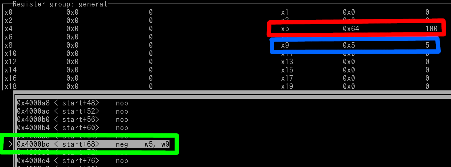
Source Register (w9) is outlined in blue and Destination Register (w5) is red. w5 currently contains the value of 0x100. However once the instruction executes, that value will be replaced. Let's say the instruction has now executed. View the following pic...
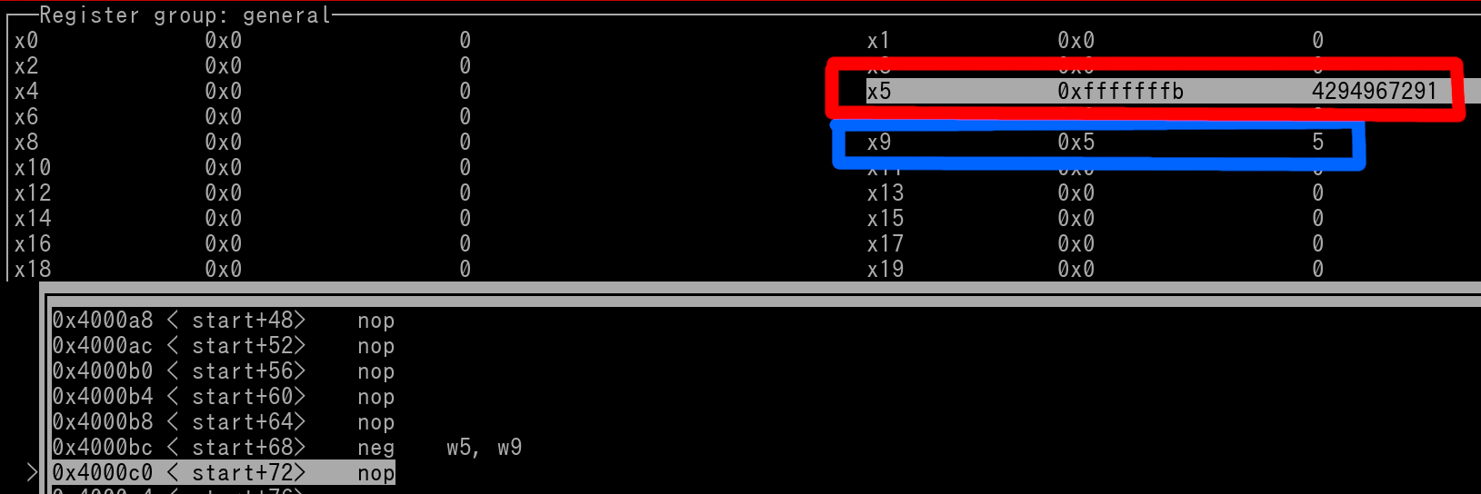
The neg instruction has resulted in w5 being -5.
Let's cover one more basic instruction, this one is important...
Move Into Register:
mov xD, SIMM32 //0xFFFFFFFFFFFF8000 thru 0x0000000000007FFF
mov wD, SIMM32 //0xFFFF8000 thru 0x00007FFF
mov xD, xA
mov wD, xA
This instruction (with the Immediate Value option) is what you can use to write values from 'scratch' into a Register. Regarding SIMM32, there's actually more options for Immediate Value Ranges, but those are a bit complex for a beginner to understand. In the next chapter, we will dive into how to write any custom value to a Register.
Let's go into some various examples of mov.
Example non-extended use of mov:
mov w16, #0x0010
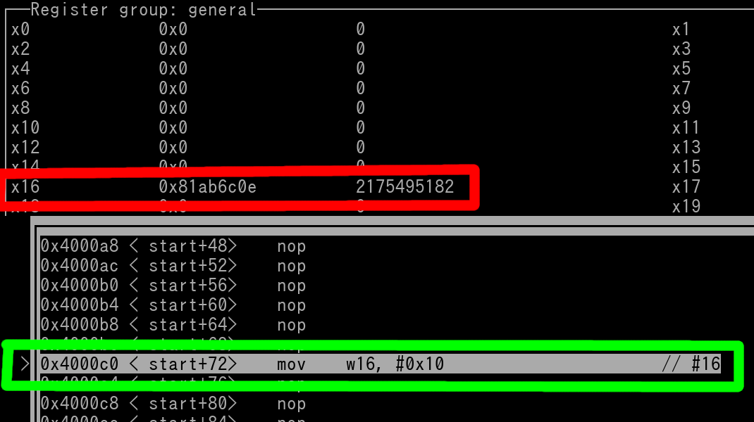
The following pic shows us the state of w16 right before the mov instruction is going to execute (outlined in Green). w16 register is outlined in red. There is currently a value in w16. It will be overwritten once the mov instruction executes...
Now let's have the mov instruction execute....
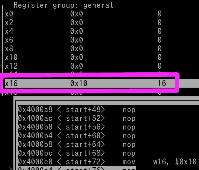
The above pic shows us that the mov instruction has now executed and w16 is now 0x10 (outlined in magenta). FYI, you can exclude leading zero(s) in Immediate Values (i.e. write 0x10 for 0x0010). Therefore, you can write the mov instruction like this...
mov w16, #0x10
Another example (extended usage) of mov:
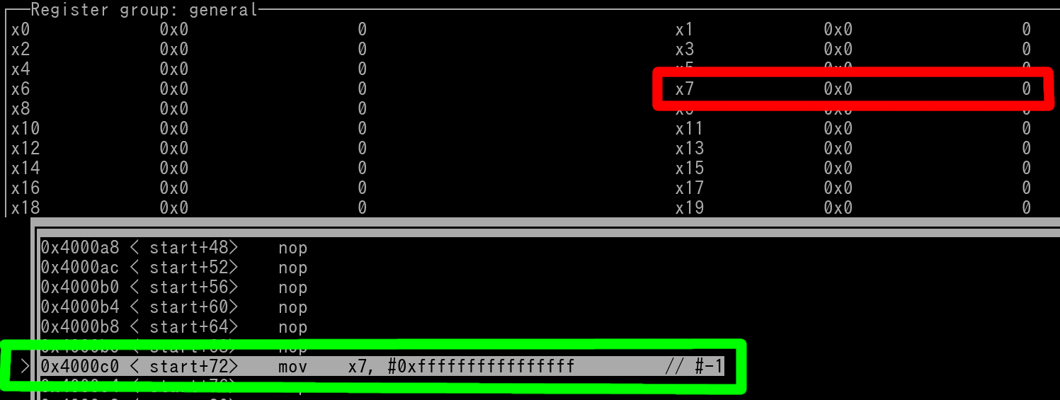
mov x7, #0xFFFFFFFFFFFFFFFF // Decimal form is -1
This instruction will set x7 to -1. You don't have to write out this very long hex value, You can use decimal representation for Immediate Values if desired. Like this..
mov x7, #-1
Here's a picture of right before the mov instruction has executed. x7 outlined in red, and the instruction (has not yet executed) is outlined in green...
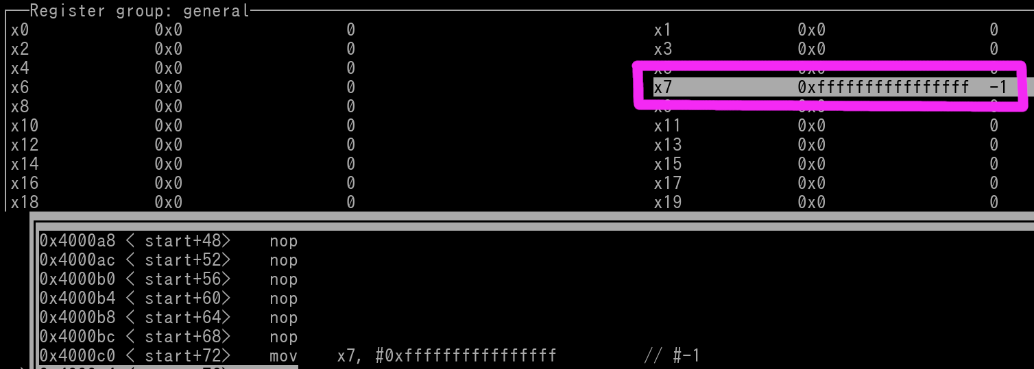
And here's the picture of once the instruction has executed. x7 is outlined in magenta.
About General Instruction flow; writing multiple Instructions in your Source File:
Instructions (except in the case of exceptions aka crashes, and branches aka jumps) execute in a top to bottom fashion. For example we have the following 3 instructions...
add x1, x10, x5 //This instruction will execute first
mov x7, -1 //This instruction executes second
mul x0, x0, x30 //And this instruction executes third
The top add instruction executes first. Then the mov will be executed. After that, the mul instruction will be executed. When writing instructions out in any Assembler, only one instruction can be present per 'line/row' in your Source File.