Chapter 27: The Stack
Now that you know how to call functions, we need to go over pushing and popping stack frames. You will know what the Stack is, how it works, how to use it for your benefit, how to write your own Prologues+Epilogues, and among other things.
At this moment you obviously have no idea of how a Prologue can save data/registers, and how an Epilogue can retrieve them. It seems like black magic.
The SP register is not a regular GPR, nor is it a regular SPR. More like a hybrid. It does not have a GPR number associated with it. We can freely read/write to SP, but there are some restrictions. For starters, you cannot just arbitrarily write to it, various functions are using SP's value. Not only that, the value in SP must be divisible by 16 (0x10). If not, you will cause an exception. Needless to say, it also must contain a valid Memory Address at all times.
Prologues of functions include instruction(s) for what is called pushing the stack. Epilogues include instruction(s) for what is called popping the stack.
Pushing the stack means to create a new stack frame. What is a stack frame? Well let's explain 4 important elements in order shown below.
The SP register holds the Memory Address that points to the very top of the Stack. The Stack contains what is called Stack Frames. At the very top of the Stack is the newest/latest Stack Frame. Therefore SP also points to the latest (current) Stack Frame.
The Stack Frame is an area of memory within the Stack that holds values of registers (plus other data) that needs to be preserved throughout function call(s). A majority of contents within the Stack Frame are previous/saved values of the Callee-Saved Registers.
As mentioned earlier, the Stack as a whole is a collection of the current stack frame and previous stack frames. When a new stack frame is created, the Stack itself grows toward LOWER memory addresses. Thus each new stack frame has a decreased memory address in comparison to the previous stack frame. Visually speaking (on a memory viewer tool), the Stack grows upward.
Since the Stack grows upward, memory above SP is technically free space to use. This free space is known as the Stack's Negative Space. There is a large upper bound limit to this, but this Negative Space shouldn't really be used as it's not "proper" and if an interrupt happens, the data in this Space will be lost/corrupted/overwritten.
x29 aka fp is known as the Frame Pointer. This will contain the Memory Address that points to location of the previous/older (pre-Prologue) x29 value that is residing in the Current/Latest Stack Frame. This allows what is known as back chaining which will be discussed later.
Four General Rules of SP and Stack Frames~
The layout format of Stack Frames varies between which Assembler you intend to use. The layout for Clang is unintuitive and less simple. GCC's layout is much better. We will follow its layout.
GCC uses the following Stack Frame layout...
Offset to SP | Item
0 | x29
0x8 | x30
0x10 | Callee_Saved Registers
0x10+ | Caller Saved Temp Registers
0x10+ | Extra Buffer Space
0x10+ | Space for Alignment
Because some items in the above layout may be excluded, we have to put "0x10+" for the last 3 categories.
In order to know how to properly create a new Frame, we will go over the most simple Function Prologue. It will create the bare minimum 16-byte Stack Frame and adjust x29 (fp) to update the back chain. Also, SP starts off with the value/address of 0x4000800260
Example:
stp fp, lr, [sp, #-0x10]!
mov fp, sp
On the first (stp) instruction, the contents of fp is stored at 0x4000800250 (SP minus 0x10). Contents of the lr is stored at 0x4000800258 (SP minus 8). Since the stp instruction is a pre-index type store instruction, once fp and lr are stored, SP gets decreased by 0x10 from 0x4000800260 to 0x4000800250. For terminology purposes, the stp instruction itself is known as "pushing the stack". That instruction alone is responsible for creating the new Stack Frame.
Remember that I said earlier that the Stack grows towards LOWER addresses. In a visual sense, on a memory viewer tool, this means new frames are created on top of the older frames.
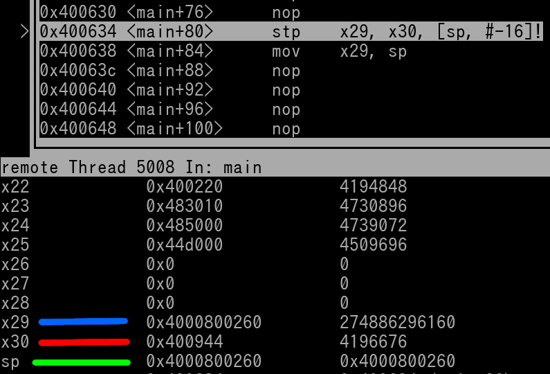
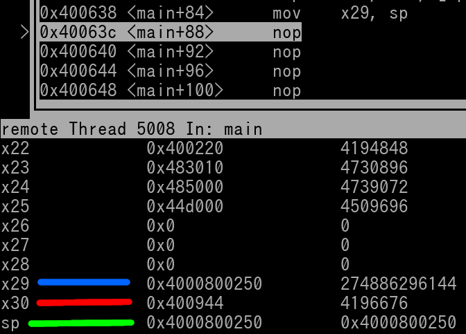
Let's look at this in GDB to get a better idea. Here's a pic of right before the instruction is executed
We see that...
x29 (fp) = 0x4000800260 (blue line)
x30 (lr) = 0x400944 (red line)
sp = 0x4000800260 (green line)
Let's step the stp instruction and see how the registers have changed
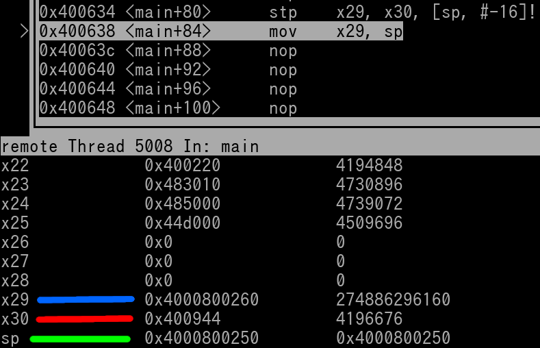
We see that...
x29 (fp) = 0x4000800260 (blue line)
x30 (lr) = 0x400944 (red line)
sp = 0x4000800250 (green line)
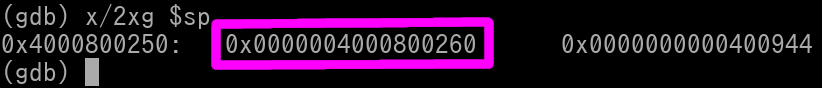
Notice that sp was decremented by 0x10. A new stack frame of 0x10 size has been created. Let's view the contents of the Stack Frame (first 16 bytes at SP's Address) in Memory...
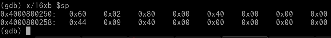
Because of Little Endian shenanigans, all the bytes within each double-word are reversed/swapped. Let's issue a different GDB Memory command to list each double-word in "Big Endian" format/style to get a better visual view
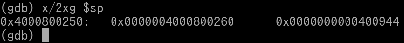
Ah. There we go. We see that x29 (The GPR's contents) has been stored at SP (the very start of the new frame). We see that x30 (GPR's contents) has been stored at SP+8.
Now at this particular moment, there is a problem. ARM64 requires that the x29/fp Register needs to always contain the Address that points to where the older/former (pre-Prologue) x29 is residing at in the current (new) Stack Frame. At this moment, the x29/fp register contains 0x4000800260. This currently does *NOT* point to where the older x29 resides in the current (new) Stack Frame
Since ARM64 also requires that the older x29/fp be placed at the very start of a new Frame whenever one has been created, we can fix the x29/fp issue with the following instruction....
mov fp, sp
This exact instruction must be present in any function that has a Prologue and it's usually the last instruction of the Prologue. Let's execute this in GDB and take a look...
We see that fp and sp are now equal. This will be a good time to explain what Back-Chaining is. Every Stack Frame (its first double-word value) contains the older/former x29. The current Frame will contain its older x29 value. This value is the address that will point to the start of the previous Stack Frame. If you proceed to that previous Stack Frame, it also contains its own relative old x29 value. That x29 value will then point to the next older Stack Frame. And so on and so on. This allows a Developer to write code for the case of crashes/exceptions to produce what is called a Stack Trace. Stack Traces are necessary to help code authors debug crashes. Whenever a Frame contains a null value at where its relative older x29 is suppose to be at, that means you have hit the very bottom of the current working Stack, as a whole.
Let's do some backchaining with what we have at the moment from the above pictures. We had just stepped thru the "mov fp, sp" instruction. Thus our new frame has been created and all necessary registers are updated correctly.
Let's review our current Stack Frame in memory again...
Notice that the old x29 (outlined in magenta) that's residing in the Frame is 0x4000800260. Let's view what is there in memory. We will adjust the GDB command to show our current frame (2 double words) and also show the next 2 double-words below. This will include, at least the old fp and lr, of the previous frame.
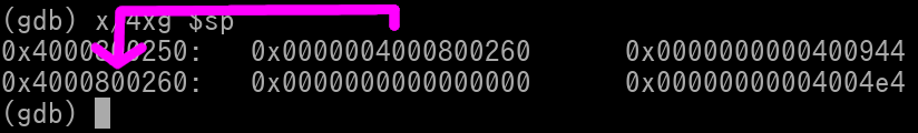
Notice that the magenta arrow is showing you how to back-chain visually. We can see there is a NULL value at where the frame's old x29 is suppose to be at. That means we've hit the bottom of the Stack. We cannot back-chain any further.
---
"Popping the stack" refers to a specific instruction within an Epilogue. Let's cover an epilogue that will handle the bare minimum frame that we've created earlier...
ldp fp, lr, [sp], #0x10
ret
The ldp instruction is the instruction that "pops the stack". Popping meaning the stack frame has been destroyed. In the ldp instruction the following occurs...
In conclusion, the ldp instruction has given us back all the former fp, lr, and sp values. The only thing left is for the function to return back using what's in the x30 (lr) register.
ret
The ret gets executed and the epilogue (function) has fully been completed.
Custom Frame Sizing:
Function(s) can preserve data by storing it inside a Stack Frame. When wanting to save data, the size of the Stack Frame to be created must be adjusted. The size used also has to be divisible by 16. Therefore, rounding up in size may be required so the 16-byte alignment is met.
This is a simple formula for calculating Stack Frame size when GPRs are the only item in question for storing onto the Frame
A function may need to backup registers in order to get itself some free registers to use for a task. When such a scenario occurs, the callee saved registers are the first to be saved. If a callee-saved register needs to be saved, the first one to be used is x19. If a function needs more, it will work its way up the register list til x28, the final callee-saved register.
For example, let's say a function will want to use 2 registers to keep some new data intact thru a child function that it contains. The Stack Frame required size is determined as such...
The Frame size will be 32, or 0x20 in hex. The prologue will be this...
stp fp, lr, [sp, #-0x20]! //Push (make) new Frame with size of 32 bytes
stp x19, x20, [sp, #0x10] //Backup (save) x19 and x20 onto the Frame
mov fp, sp //Update fp to update the back chain
With this prologue, let's view what the Stack Frame layout would look like....
SP Offset | Item
0 | fp
0x8 | lr
0x10 | x19
0x18 | x20
As you can see we did the store-pair of x19 & x20 at the offset of 0x10 relative to SP because we don't want to overwrite the fp and lr that was just saved.
The epilogue for the above prologue would be this...
ldp x19, x20, [sp, #0x10] //Restore old x19 and x20
ldp fp, lr, [sp], 0x20 //Restore old fp, lr, and sp. Frame is popped (destroyed)
ret //End function, return to Caller
---
Ok, let's step it up a bit. Let's say we have a function that needs to backup 5 GPRs. Let's calculate the Frame size...
Frame size will be 64 bytes in size (0x40 in hex). The prologue will be this...
stp fp, lr, [sp, #-0x40]! //Push (make) new Frame with size of 64 bytes
stp x19, x20, [sp, #0x10] //Backup (save) x19 and x20 onto the Frame
stp x21, x22, [sp, #0x20] //Backup x21 and x22
str x23, [sp, #0x30] //Backup x23
mov fp, sp //Update fp to update the back chain
Here's the Stack Frame layout once the prologue has been completed
SP Offset | Item
0 | fp
0x8 | lr
0x10 | x19
0x18 | x20
0x20 | x21
0x28 | x22
0x30 | x23
0x38 | 8 bytes of extra space for alignment
As you can see the alignment space goes at the very bottom/end of the frame. And here's the epilogue...
ldr x23, [sp, #0x30]
ldp x21, x22, [sp, #0x20]
ldp x19, x20 [sp, #0x10]
ldp fp, lr, [sp], #0x40
ret
Storing Floats to Stack:
Only the lower 64-bits of the FPR needs to be saved if being stored into a stack frame. However, if you are handwriting custom functions, you may have scenarios where this may not apply, and you need to save the entire 128-bit FPR.
For calculating stack size for FPR, usage of the same equation is required
However! For custom handwritten functions in a scenario where you need to backup the entire FPR, you must change the 1st step of the equation to this...
Number of FPRs x 16 = Sub-Total 1
For a prologue of 2 GPRs and 1 FPR, we need a Frame size of 42 (0x30) bytes.
Example prologue saving 2 GPRS and 1 FPR; lower 64-bits only:
stp fp, lr, [sp, #-0x30]!
stp x19, x20, [sp, #0x10]
str d8, [sp, #0x20]
mov fp, sp
Frame layout after prologue:
SP Offset | Item
0 | fp
0x8 | lr
0x10 | x19
0x18 | x20
0x20 | d8
0x28 | 8 bytes of extra space for alignment
Epilogue:
ldr d8, [sp, #0x20]
ldp x19, x20, [sp, #0x10]
ldp fp, lr, [sp], #0x30
ret
Allocating Buffer Space in a Stack Frame:
There may be times a function will allocate extra Frame size/space for buffer(s) of a child function.
Some functions may require a Register Argument for a Memory Address that is used as a pointer for said function to write some output information to. This is known as an Output Buffer. A function may require a Register Argument to be a Memory Address that points to a small size of memory. The contents in that small segment of memory will be processed by a Function to do a task. This is known as an Input Buffer.
Buffer Space always goes last in the Stack Frame layout, excluding any extra space required for alignment. Let's say we need to allocate 98 bytes of buffer space in a Prologue and nothing else. The Stack Frame would need to be 128 (0x80) bytes in size. The prologue would be this....
stp fp, lr, [sp, #-0x80]! // Push frame of 128 bytes in size, backup fp and lr
mov fp, sp //Update fp to update back chain
The stack frame size is 128 bytes in size because....
16 (for fp and lr) + 98 (buffer) = 114
114 must be rounded up to 128 (0x80 in hex) to be divisible by 16
The stack frame's layout after the Prologue is this...
SP Offset | Item
0 | fp
0x8 | lr
0x10 | 98 bytes of buffer space
0x72 | 14 bytes extra space for alignment
The corresponding epilogue is this...
ldp fp, lr, [sp], #0x80
ret
Final Example:
Here's a prologue and epilogue for backing-up/restoring 3 GPRs, 2 FPRs (lower 64 bits only), and 48 bytes (0x30) of buffer space
//Frame size 112 (rounded up from 104)= {(3 x 8) + (2 x 8) + 48 + 16}
Prologue:
stp fp, lr, [sp, #-0x70]! // 112 = 0x70
stp x19, x20, [sp, #0x10]
str x21, [sp, #0x20]
stp d8, d9, [sp, #0x28]
mov fp, sp
Stack Frame Layout after Prologue:
SP Offset | Item
0 | fp
0x8 | lr
0x10 | x19
0x18 | x20
0x20 | x21
0x28 | d8
0x30 | d9
0x38 | 48 (0x30) bytes of buffer space
0x68 | 8 bytes of space for alignment
Epilogue:
ldp d8, d9, [sp, #0x28]
ldr x21, [sp, #0x20]
ldp x19, x20, [sp, #0x10]
ldp fp, lr, [sp], #0x70
ret